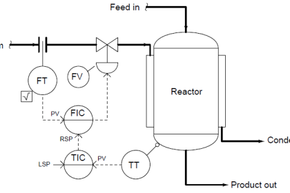
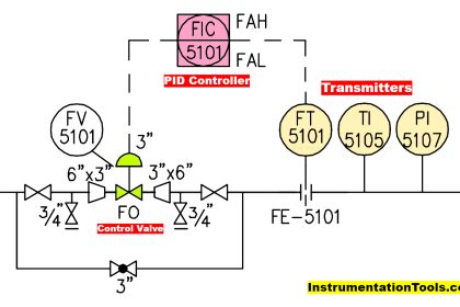
Examine these pressure and level control loops (transmitter-controller-valve systems) for an industrial boiler, controlling both water level and steam pressure:
Pressure and Level Control Loops

If the PIC setpoint is 225 PSI and the measured steam pressure begins to rise above that value, how should the PIC respond, and how will this response bring the steam pressure back down to setpoint?
Describe a situation where the block and bypass hand valves installed on the fuel gas line might ever be used, either by operations or by maintenance personnel.
If the I/P transducer on the level control loop suddenly fell out of calibration in such a way that it output a pneumatic signal that was too low, how would this affect the control of water level in the steam drum?
Answer:
If steam pressure begins to fall below setpoint, the PIC should send a decreasing signal to the fuel gas valve, causing the burner to output less heat and thereby lowering the steam pressure to setpoint again. If well-tuned, a loop controller will drive its output signal to whatever value is necessary to achieve PV = SP.
The manual block and bypass valves are useful for taking the fuel control valve out of service while the boiler is still running. This allows technicians to stroke-test and even replace the control valve without shutting down the boiler. I will let you describe and explain the sequence of valve motions necessary to take a working control valve out of service. (use comments section to share your way of doing it.)
A falsely-low pressure signal coming from the I/P might cause the actual water level to drop if the change was sudden, but the LIC will eventually compensate for this change by adjusting its output signal value until the control valve is at the correct position again.
Questions for you
Explain what would happen to this process if the air supply to the feedwater valve’s I/P transducer failed.
Explain what would happen to this process if the air supply to the fuel valve’s I/P transducer failed.
Explain how both control loops will respond to a sudden increase in steam demand.
Share Your Answers with us through comments.
Read Next:
- Pressure Loop Wiring
- Voltage Drops at Flow Rates
- Pneumatic Control Loop
- Loop Controller HART Noise
- Calibrator 4-20 mA Signal
Credits: Tony R. Kuphaldt


Answer: I am trying to giving an answer just with a basic knowledge of Control loops
1) Assuming that Feedwater valve is ATO, if air supply fails, then feedwater shut off, hence water drum level start decreasing and at the same time PIC loop maintains the Fuel supply such that Steam demand fulfills. but due to shortage of water in drum or tubes, the burner may rupture the tubes if fuel supply not shut.
2) Assuming that Fuel Supply valve is ATO, if air supply fails, then Fuel Supply shut off and burner also stops. Hence water doesn’t get converted into steam, and steam demand goes on increasing.
3)If there is sudden increase in Steam demand, then PIC Loop open more Fuel Supply Valve to generate more steam, and results to decrease in water level, hence at the same time LIC Loop will open more Feedwater valve to compensate for water level demand.