This is a PLC Program for a fan control unit system for industry. Learn the PLC ladder diagrams with example problems.
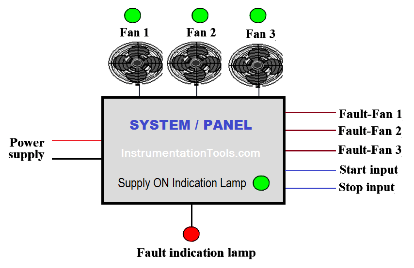
There are three fans in a system. During the system running two fans must be running out of three fans.
Implement the logic for the fan control unit in PLC using the ladder diagram programming language.
For this application, we used S7-300 PLC and TIA portal software for programming.
We used latching circuit for cycle ON (M0.0) coil. It can be started by pressing START PB (I0.0) and stop by pressing STOP PB (I0.1). Main switch (I2.0) must be ON.
When cycle is ON (M0.0) and fan 2 and fan3 faults are not present, fan2 (Q0.1) and fan 3(Q0.2) will be ON.
Either Fan 2 or Fan 3 is faulty, fan 1 will be activated (Q.0).
In system if any two fans out of three are faulty, fault indication lamp (Q0.3) will begin flickering with 5HZ frequency.
Indication lamps for fan 1, fan 2 and fan 3.Lamp will be activated according to fault signal.
When main switch is ON (I2.0), main supply ON indication lamp (Q0.7) will be ON.
Note :- Above application may be different from actual application. This example is only for explanation purpose only. We can implement this logic in other PLC also. This is the simple concept of fan control unit used in industry, we can use this concept in other examples also.
All parameters considered in example are for explanation purpose only, parameters may be different in actual applications. Also all interlocks are not considered in the application.
If you liked this article, then please subscribe to our YouTube Channel for PLC and SCADA video tutorials.
You can also follow us on Facebook and Twitter to receive daily updates.
Read Next:
Learn the example of flip-flop PLC program for lamps application using the ladder logic to…
In this article, you will learn the STAR DELTA programming using PLC controller to start…
Lube oil consoles of rotary equipment packages in industrial process plants are usually equipped with…
Rotating equipment packages such as pumps, compressors, turbines need the lube oil consoles for their…
This article explains how to blink lights in ladder logic with a detailed explanation video…
In this article, a simple example will teach you the conversion from Boolean algebra to…


View Comments
Sir can you suggest any simulator software for s7 300 plc. So that young aspirants can practice all these helpful program sections.
good