Inst ToolsInst ToolsInst Tools
  • Courses
  • Automation
    • PLC
    • Control System
    • Safety System
    • Communication
    • Fire & Gas System
  • Instrumentation
    • Design
    • Pressure
    • Temperature
    • Flow
    • Level
    • Vibration
    • Analyzer
    • Control Valve
    • Switch
    • Calibration
    • Erection & Commissioning
  • Interview
    • Instrumentation
    • Electrical
    • Electronics
    • Practical
  • Q&A
    • Instrumentation
    • Control System
    • Electrical
    • Electronics
    • Analog Electronics
    • Digital Electronics
    • Power Electronics
    • Microprocessor
  • Request
Search
  • Books
  • Software
  • Projects
  • Process
  • Tools
  • Basics
  • Formula
  • Power Plant
  • Root Cause Analysis
  • Electrical Basics
  • Animation
  • Standards
  • 4-20 mA Course
  • Siemens PLC Course
Reading: PLC Program for Alarm Security System
Share
Font ResizerAa
Inst ToolsInst Tools
Font ResizerAa
  • Courses
  • Design
  • PLC
  • Interview
  • Control System
Search
  • Courses
  • Automation
    • PLC
    • Control System
    • Safety System
    • Communication
    • Fire & Gas System
  • Instrumentation
    • Design
    • Pressure
    • Temperature
    • Flow
    • Level
    • Vibration
    • Analyzer
    • Control Valve
    • Switch
    • Calibration
    • Erection & Commissioning
  • Interview
    • Instrumentation
    • Electrical
    • Electronics
    • Practical
  • Q&A
    • Instrumentation
    • Control System
    • Electrical
    • Electronics
    • Analog Electronics
    • Digital Electronics
    • Power Electronics
    • Microprocessor
  • Request
Follow US
All rights reserved. Reproduction in whole or in part without written permission is prohibited.
Inst Tools > Blog > PLC Tutorials > PLC Program for Alarm Security System

PLC Program for Alarm Security System

This is the PLC Program for Alarm Security Systems. Learn the PLC programming with this example problem.

Last updated: November 3, 2023 11:58 am
Editorial Staff
PLC Tutorials
No Comments
Share
4 Min Read
SHARE

This is the PLC Program for Alarm Security Systems. Learn the PLC programming with this example problem.

Contents
Alarm Security SystemProblem DiagramProblem SolutionList of Inputs and OutputsPLC Ladder Diagram for Alarm Security SystemProgram DescriptionResult

Alarm Security System

Problem Description

Make burglar alarm system program in S7-1200 PLC for the house.

Consider one house, in this we want to arrange automatic burglar alarm security system. Alarm should be ON when any person will be detected by the motion sensor.

Problem Diagram
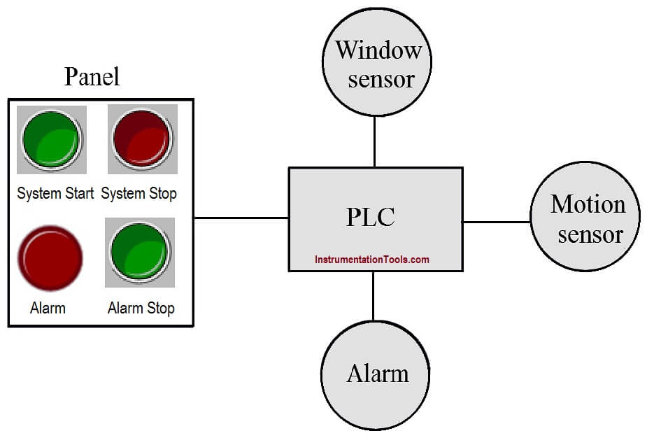
PLC Program for Burglar Alarm Security System

Problem Solution

We can solve this problem by using simple logic. Here we can use two sensors, one motion sensor and second window sensor. Window sensor is the loop of wires.

The motion sensor is designed such that when person is detected in a house or room, then the sensor will be activated (change its state to 1 or true)

Here important point in window sensor is that current is always passing until the breakage occurs in the glass. Hence output always true and when someone will try to break the window glass, current will not flow in the circuit.

List of Inputs and Outputs

Inputs List

  • System START :- I0.0
  • System STOP :- I0.1
  • Motion detector :- I0.2
  • Window sensor :- I0.3
  • Alarm stop button :- I0.4

Outputs List

  • Alarm :- Q0.0

M Memory

  • M0.0 :- Master coil.
  • M0.1 :- Alarm on condition.

PLC Ladder Diagram for Alarm Security System
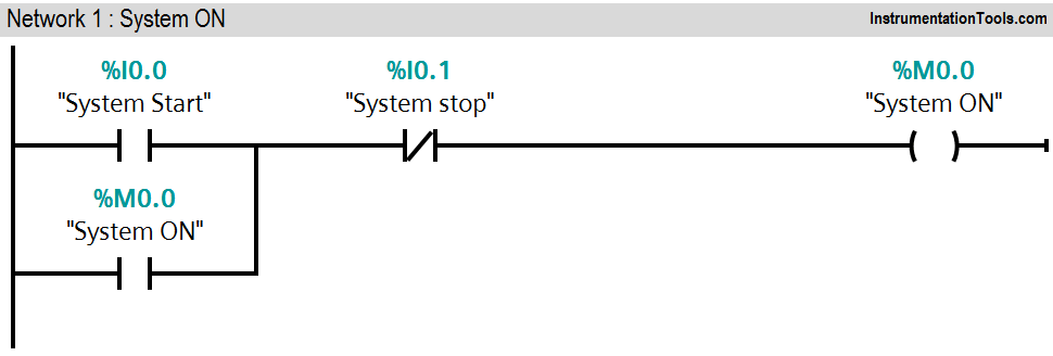
PLC Logic for Alarm Security Systems
PLC Alarm System
PLC Burglar System

Program Description

In this problem we will consider S7-1200 PLC and TIA portal software for programming.

Network 1:

This network shows simple latching circuit for system ON and system OFF.

we used Normally Open (NO) contact of system START button (I0.0) and NC contact of system STOP button (I0.1) for system activation.

Network 2:

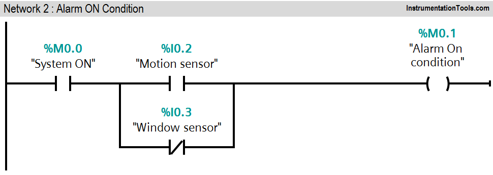
When system is activate and motion sensor (I0.2) detects the person entry, alarm on (M0.1) condition will be ON and it will activate the alarm (Q0.0).

Normally NC contact of window sensor (I0.3) is used in parallel so in normal condition it is true. If breakage of glass or window condition is detected, window sensor (I0.3) input goes false and it will activate the alarm condition (M0.1).

Network 3:

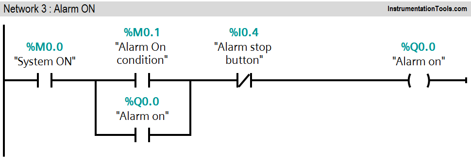
In this network latching circuit is used for alarm (Q0.0). If alarm condition is detected (M0.1), alarm will be ON and it can be stopped by pressing alarm STOP PB (I0.4).

Note :- Above logic is for explanation purpose only. We can implement this example by using hard wired relay logic also. S7-1200 PLC system is so costly for this simple system.

Result

PLC based Security System

Author: Bhavesh

If you liked this article, then please subscribe to our YouTube Channel for PLC and SCADA video tutorials.

You can also follow us on Facebook and Twitter to receive daily updates.

Read Next:

  • PLC Program for Motor Starter
  • Analog Input Sampling in PLC
  • Positive Edge Output for One Cycle
  • Automatic Liquid Mixing Application
  • PLC Program START & STOP Buttons
Don't Miss Our Updates
Be the first to get exclusive content straight to your email.
We promise not to spam you. You can unsubscribe at any time.
Invalid email address
You've successfully subscribed !

Continue Reading

RSLogix 5000 PLC Programming Procedure
How to Work with Delta PLC Simulator?
Allen Bradley PLC Subroutines
InTouch SCADA Login Password Security
Connecting Blocks in Functional Block Diagram – Studio 5000
PLC Fault Diagnosis – PLC Training Documents
Share This Article
Facebook Whatsapp Whatsapp LinkedIn Copy Link
Share
Leave a Comment

Leave a Reply Cancel reply

Your email address will not be published. Required fields are marked *

Stay Connected

128.3kFollowersLike
69.1kFollowersFollow
210kSubscribersSubscribe
38kFollowersFollow

Categories

Explore More

Configuration of Input and Output Tags in Siemens Scada and PLC
LIFO Instruction in PLC
Overview of SIEMENS PLC – S7-1500, S7-1200, S7-400, S7-300
PLC based 4 Way Traffic Light Control System
Face Mask Making Machine using PLC and HMI
One Shot Rising and One Shot Falling Instructions in PLC
What is a Tag? Types of Tags in SCADA
Mail Box Automation: Programming with Schneider PLC

Keep Learning

PLC Valve Control Example

Create a Function (FC) for a Valve Logic in Siemens PLC

Classic Control Circuits

Motor Classic Control Circuits using Single Push button

Instrumentation Design Details

I&C Engineer Roles & Responsibilities – Instrumentation Design

Bit Shift Registers PLC Program

PLC Light Sequence Control using Bit Shift Registers

PLC based Automatic Bell System

PLC based Automatic Bell System for a School

Siemens PLC Force LED

Forcing and Modifying PLC Logic

Free Download PLC Book

Free Download Programmable Logic Controller (PLC) Book

SR Flip Flop Logic

How to implement SR Flip Flop using PLC Ladder Logic

Learn More

DP transmitter with Manifold

Pressure Transmitter Manifolds

Electrical Machines Questions and Answers

Synchronous Motor Power Factor Correction Questions

Top 100 PLC Objective Questions and Answers

Top 100 PLC Objective Questions and Answers

Why Are Neutral and Earth Separated

Why Are Neutral and Earth Separated?

Digital Electronics Objective Questions

Digital Electronics Objective Questions – Set 6

PLC Logic for Water Pumping and Chemical Addition

Developing PLC Logic for Water Pumping and Chemical Addition

Top 100 555 Timer Projects for Engineering Students

Top 555 Timer Projects for Engineering Students

Computer Networks Multiple Choice Questions

150 Computer Networks Multiple Choice Questions and Answers

Menu

  • About
  • Privacy Policy
  • Copyright

Quick Links

  • Learn PLC
  • Helping Hand
  • Part Time Job

YouTube Subscribe

Follow US
All rights reserved. Reproduction in whole or in part without written permission is prohibited.
Welcome Back!

Sign in to your account

Username or Email Address
Password

Lost your password?