Learn how to create PLC program based on logic circuit to enhance your automation skills with our tutorials and videos.
Important: This PLC logic is solely for educational purposes and helps students and technicians grasp PLC fundamental concepts.
Create PLC Program
Problem Statement:
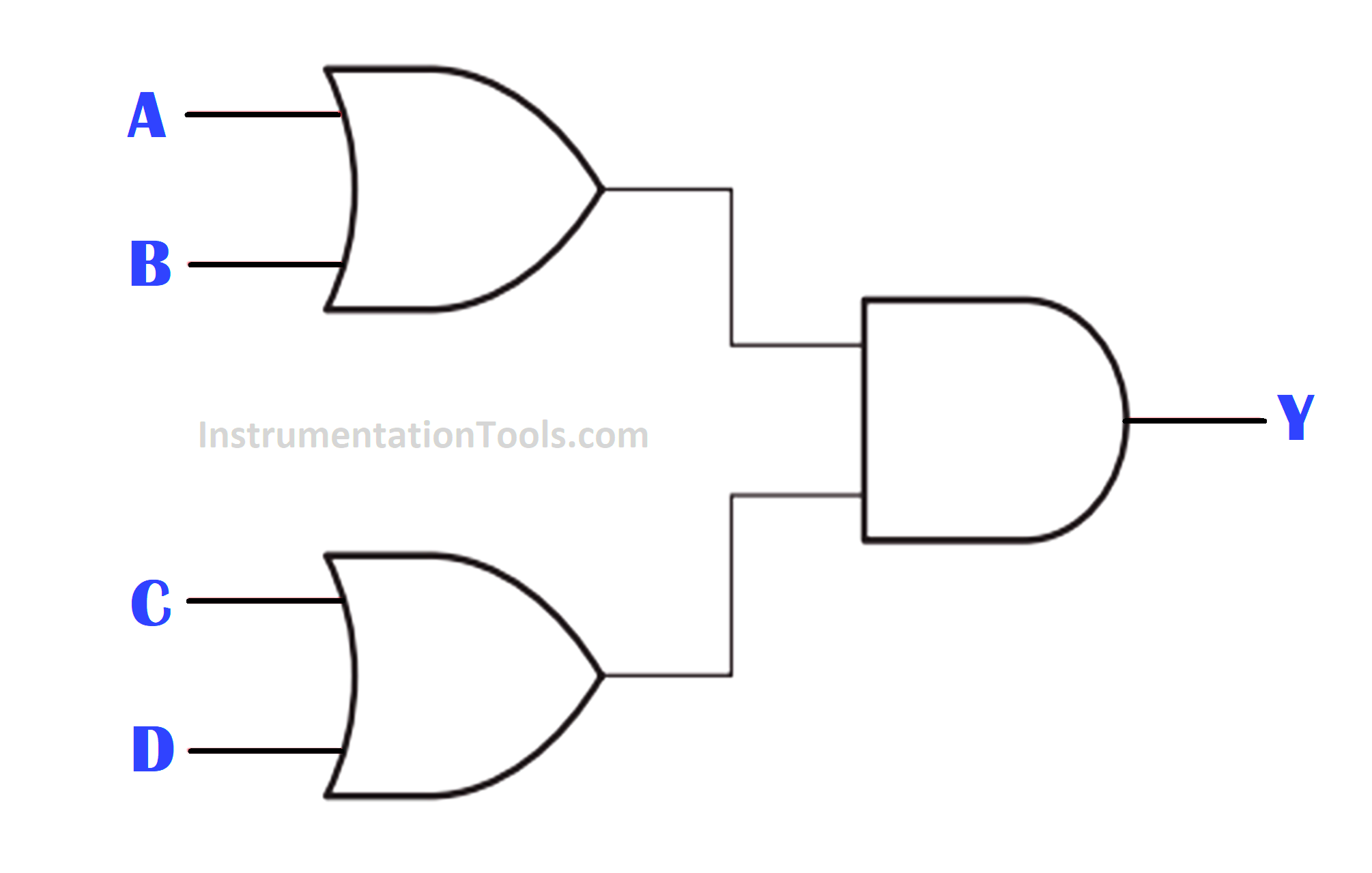
Design a PLC ladder logic for the following Logic Circuit.
We are using toggle Inputs to control the output.
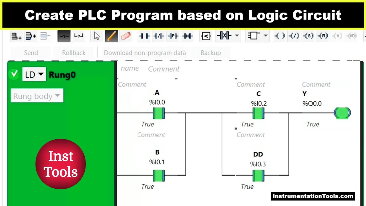
PLC Tutorial Video
Watch the video to understand the PLC concepts for a beginner level.
Inputs
The list of DI signals is listed below.
A: I0.0
B: I0.1
C: I0.2
D: I0.3
Outputs
The list of DO signals is listed below.
Y: Q0.0
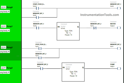
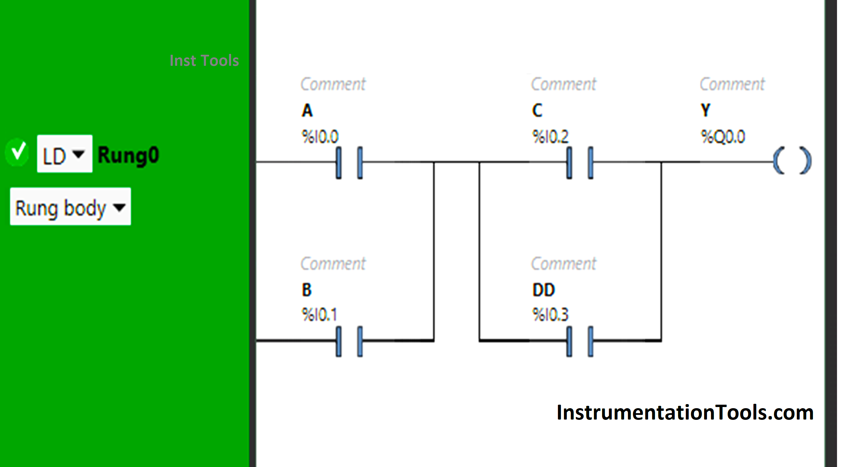
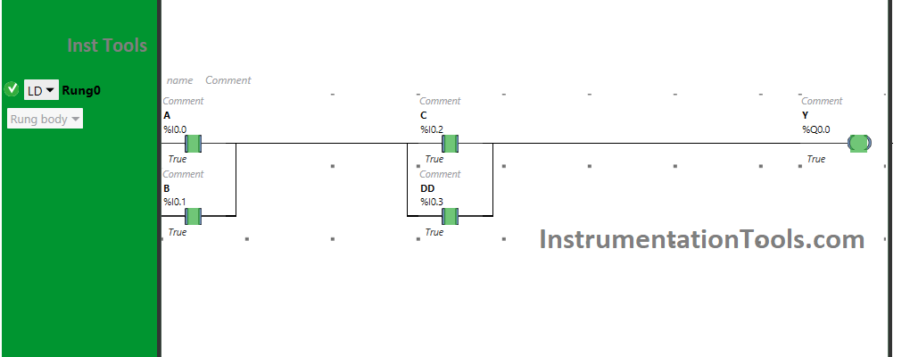
Ladder Diagram
PLC Program Explanation
- Here we used Schneider Electric PLC programming software. You can try any other PLC software too.
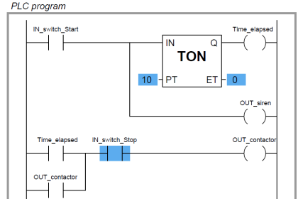
- In this PLC program, Normally Open Contacts are used for input A, input B, input C, and input D.
- Input A and Input B are connected in parallel, thus implementing OR Logic Gate.
- There is again the implementation of OR Logic Gate as Input C and Input D are connected in parallel.
- AND Logic Gate is also implemented as A + B is connected in series with C + D.
- For the output Y (Q0.0) to be ON, Input A or Input B and Input C or Input D should be ON.
PLC Test Results
The PLC program test results with different inputs are shown below.
When Input A and Input C are ON
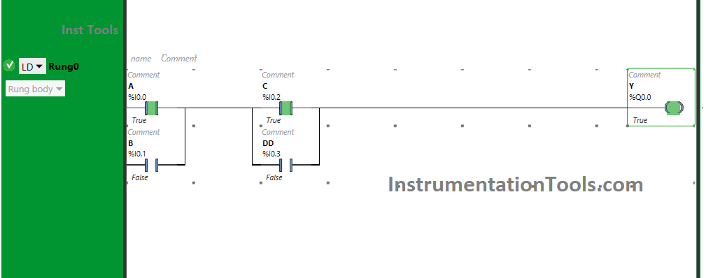
The signal will flow through Input A and Input C when these Inputs are turned ON as Normally Open Contact is used. As a result, the output Y (Q0.0) will turn ON.
When Input A and Input D are ON
When Input A and Input D are ON, Y(Q0.0) will turn ON as Normally Open Contacts used for these Inputs are in True state.
Instead of using input C, we can also use input D to turn ON the output Y (Q0.0).
When Input B and Input C are ON

The output Y (Q0.0) will turn ON when Normally Open Contacts used for Input B and Input C are in True state and will pass signal to flow.
Here, instead of using input B, we can also use input B to turn ON the output Y (Q0.0).
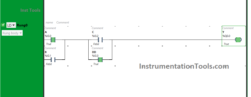
When Input B and Input D are ON

Turning On Input B and Input D will turn ON Y(Q0.0), as the signal will flow through Input B and Input D and will turn ON (YQ0.0).
Therefore, we can also use input B and input D to turn ON the output Y (Q0.0).
When three inputs are ON
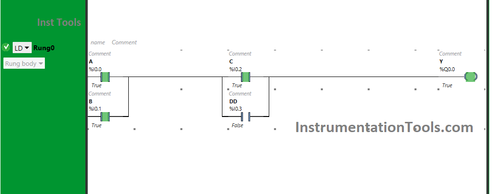

When three inputs i.e., either input A, input B, and input C or input A, input B, and input D or input B, input C, and input D are turned ON, then the output Y (Q0.0) will turn ON.
For output Y (Q0.0) to be ON, two inputs i.e., input A and input C or input D or input B and input C or input B and input D should be ON.
Turning ON the third input will not turn OFF the output Y (Q0.0). Therefore, if any three inputs are turned ON, the output will be ON.
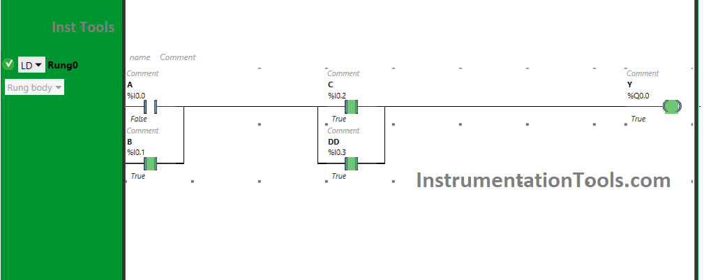
When all Inputs are ON
When Input A, Input B Input C, and Input D, all are turned ON, the output Y (Q0.0) will be ON. Turning ON all the inputs will not turn OFF the output Y (Q0.0).
If you liked this article, please subscribe to our YouTube Channel for PLC and SCADA video tutorials.
You can also follow us on Facebook and Twitter to receive daily updates.
Read Next:
- PLC Motor Logic with Pushbuttons
- Basic PLC Alarm Programming Example
- Compare CompactLogix and ControlLogix
- Standard 4 to 20 mA Conversion Formula
- Start Stop of one Motor PLC program