Inst ToolsInst ToolsInst Tools
  • Ask
  • Courses
  • Videos
  • Q & A
    • Interview
      • Instrumentation
      • Electronics
      • Electrical
      • Practical Questions
    • MCQ
      • Instrumentation MCQ
      • Electrical MCQ
      • Electronics MCQ
      • Control Systems MCQ
      • Analog Electronics MCQ
      • Digital Electronics MCQ
      • Power Electronics MCQ
      • Microprocessor MCQ
      • Multiple Choice Questions
  • EE
    • Electronics
      • Electronics Q & A
      • Electronic Basics
      • Electronic Devices & Circuits
      • Electronics Animation
      • Digital Electronics
    • Electrical
      • Electrical Basics
      • Electrical Q & A
      • Power Electronics
      • Electrical Machines
      • Electrical Animation
      • Power Systems
      • Switchgear & Protection
      • Transmission & Distribution
  • Measure
    • Control Valves
    • Calibration
    • Temperature
    • Pressure
    • Flow
    • Level
    • Analyzers
    • Switches
    • Vibration
    • Solenoid Valve
  • Control
    • PLC Tutorials
    • Control Systems
    • Safety Instrumented System (SIS)
    • Communication
    • Fire & Gas System
  • More
    • Design
    • Tools
    • Animation
    • Basics
    • Formulas
    • Standards
    • TextBooks
    • Common
    • Software
    • Excel Tools
    • Erection & Commissioning
    • Process Fundamentals
    • Videos
    • Books
Search
All rights reserved. Reproduction in whole or in part without written permission is prohibited.
Reading: Create PLC Program based on Logic Circuit
Share
Notification Show More
Font ResizerAa
Inst ToolsInst Tools
Font ResizerAa
  • Courses
  • PLC Tutorials
  • Control Systems
Search
  • Ask
  • Courses
  • Videos
  • Q & A
    • Interview
    • MCQ
  • EE
    • Electronics
    • Electrical
  • Measure
    • Control Valves
    • Calibration
    • Temperature
    • Pressure
    • Flow
    • Level
    • Analyzers
    • Switches
    • Vibration
    • Solenoid Valve
  • Control
    • PLC Tutorials
    • Control Systems
    • Safety Instrumented System (SIS)
    • Communication
    • Fire & Gas System
  • More
    • Design
    • Tools
    • Animation
    • Basics
    • Formulas
    • Standards
    • TextBooks
    • Common
    • Software
    • Excel Tools
    • Erection & Commissioning
    • Process Fundamentals
    • Videos
    • Books
Follow US
All rights reserved. Reproduction in whole or in part without written permission is prohibited.
Inst Tools > Blog > PLC Tutorials > Create PLC Program based on Logic Circuit

Create PLC Program based on Logic Circuit

Learn how to create PLC program based on logic circuit to enhance your automation skills with our tutorials and videos.

Last updated: April 4, 2024 3:22 pm
Editorial Staff
PLC Tutorials
No Comments
Share
5 Min Read
SHARE

Learn how to create PLC program based on logic circuit to enhance your automation skills with our tutorials and videos.

Contents
Create PLC ProgramPLC Tutorial VideoInputsOutputsLadder DiagramPLC Program ExplanationPLC Test Results

Important: This PLC logic is solely for educational purposes and helps students and technicians grasp PLC fundamental concepts.

Create PLC Program

Problem Statement:

Design a PLC ladder logic for the following Logic Circuit.

We are using toggle Inputs to control the output.
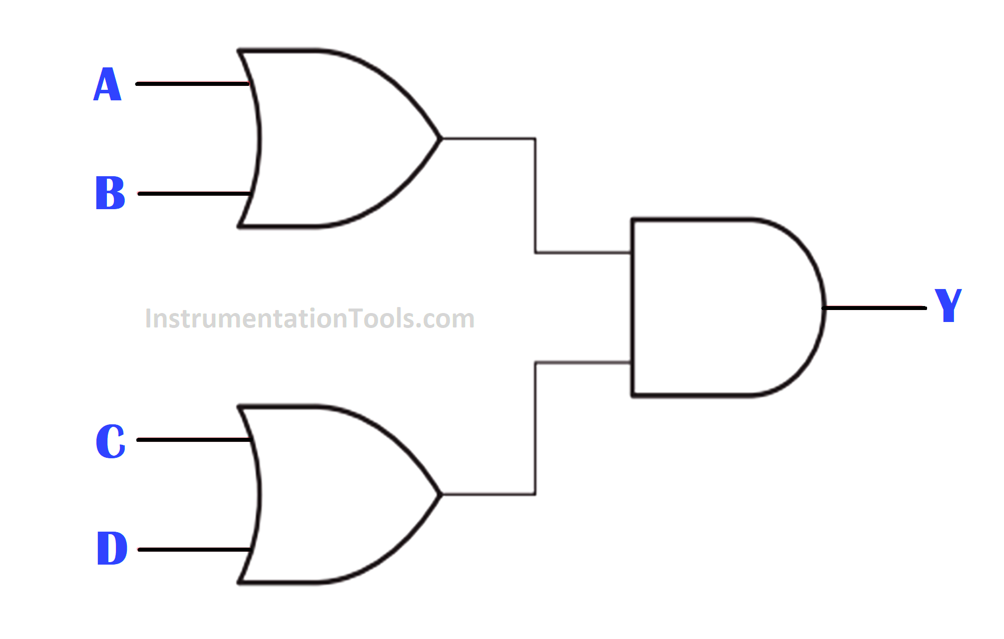
Create PLC Program based on Logic Circuit

PLC Tutorial Video

Watch the video to understand the PLC concepts for a beginner level.

Inputs

The list of DI signals is listed below.

A: I0.0

B: I0.1

C: I0.2

D: I0.3

Outputs

The list of DO signals is listed below.

Y: Q0.0

Ladder Diagram
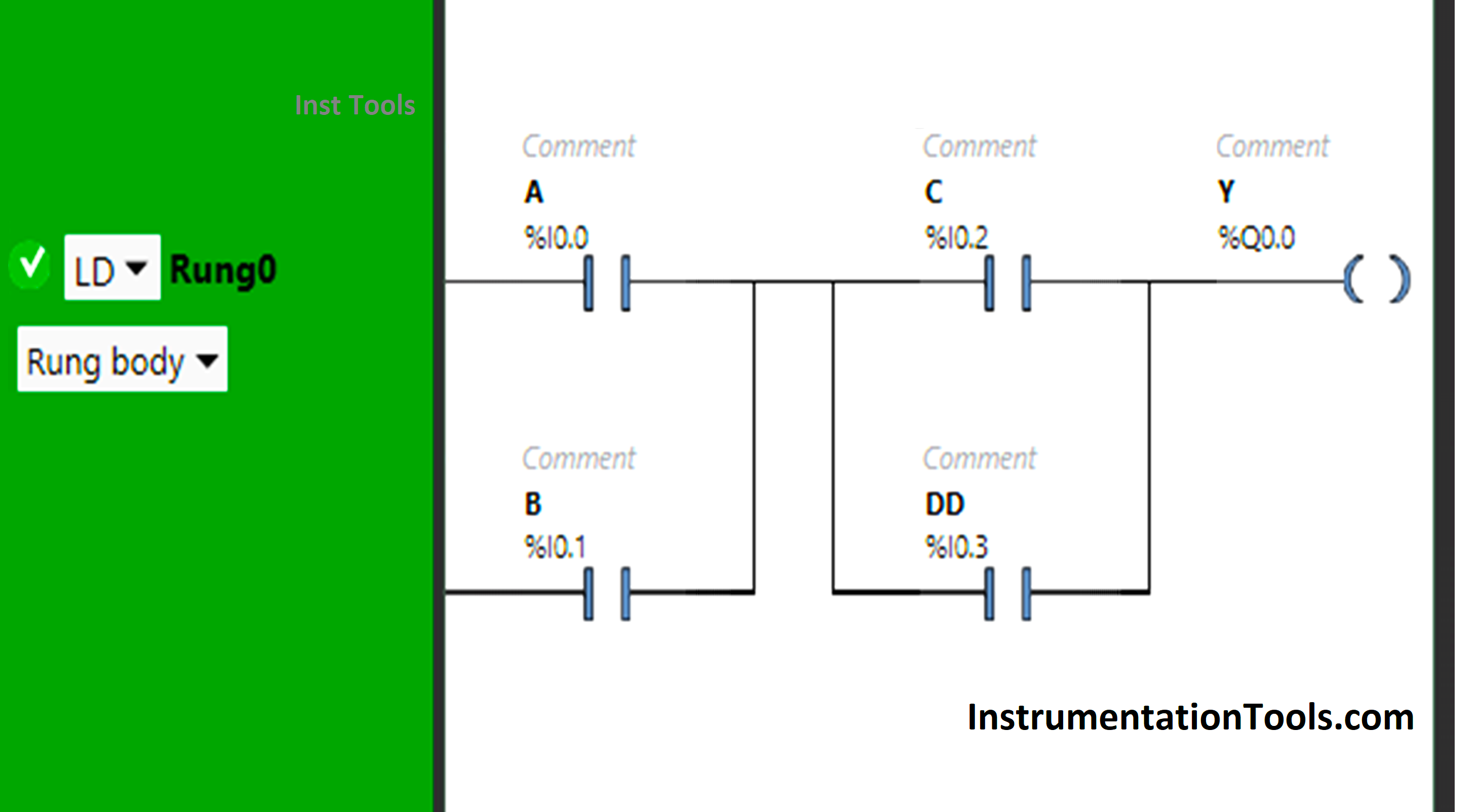
Boolean Algebra to PLC Logic

PLC Program Explanation

  • Here we used Schneider Electric PLC programming software. You can try any other PLC software too.
  • In this PLC program, Normally Open Contacts are used for input A, input B, input  C, and input D.
  • Input A and Input B are connected in parallel, thus implementing OR Logic Gate.
  • There is again the implementation of OR Logic Gate as Input C and Input D are connected in parallel.
  • AND Logic Gate is also implemented as  A + B is connected in series with C + D.
  • For the output Y (Q0.0) to be ON, Input A or Input B and Input C or Input D should be ON.

PLC Test Results

The PLC program test results with different inputs are shown below.

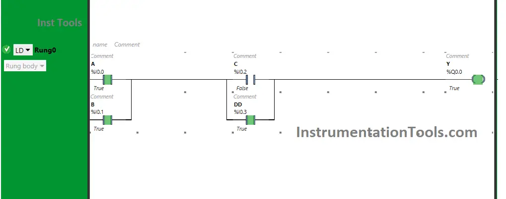
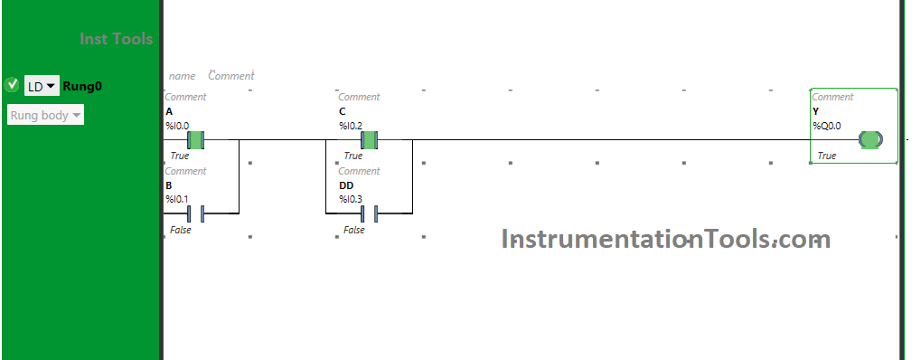
When Input A and Input C are ON
Boolean Algebra for PLC

The signal will flow through Input A and Input C when these Inputs are turned ON as Normally Open Contact is used. As a result, the output Y (Q0.0) will turn ON.

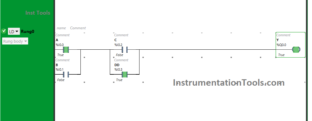
When Input A and Input D are ON
PLC Logic design with boolean expression

When  Input A and Input D are ON, Y(Q0.0) will turn ON as Normally Open Contacts used for these Inputs are in True state.

Instead of using input C, we can also use input D to turn ON the output Y (Q0.0).

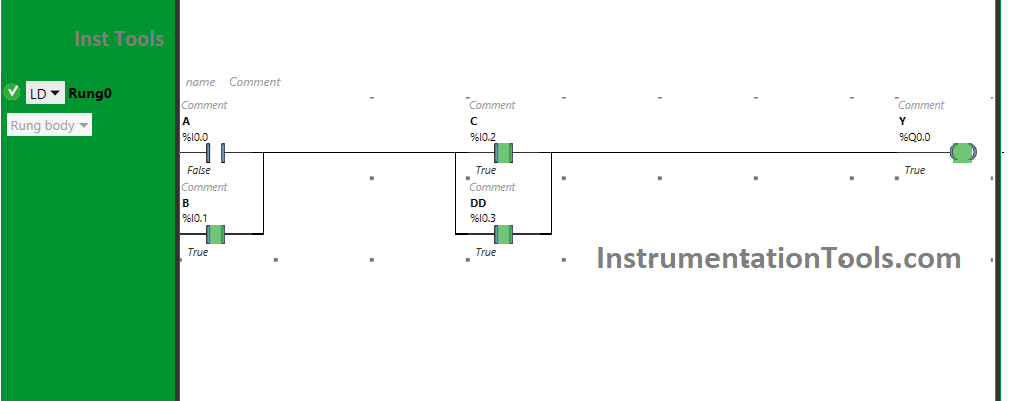
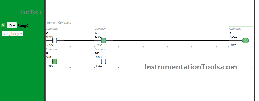
When Input B and Input C are ON
Boolean to Ladder Logic Converter

The output Y (Q0.0) will turn ON when Normally Open Contacts used for Input B and Input C are in True state and will pass signal to flow.

Here, instead of using input B, we can also use input B to turn ON the output Y (Q0.0).

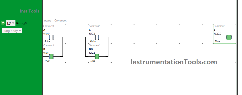
When Input B and Input D are ON
Boolean expression for the given PLC ladder program

Turning On Input B and Input D will turn ON Y(Q0.0), as the signal will flow through Input B and Input D and will turn ON (YQ0.0).

Therefore, we can also use input B and input D to turn ON the output Y (Q0.0).

When three inputs are ON
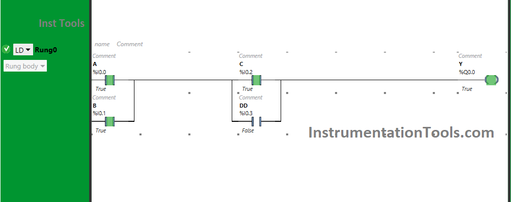
Implementing a PLC Program with Logic
Fig-1
PLC Program Utilizing Logic Circuitry
Fig-2
PLC Application with Circuit Logic
Fig-3

When three inputs i.e., either input A, input B, and input C or input A, input B, and input D or input B, input C, and input D are turned ON, then the output Y (Q0.0) will turn ON.

For output Y (Q0.0) to be ON, two inputs i.e., input A and input C or input D or input B and input C or input B and input D should be ON.

Turning ON the third input will not turn OFF the output Y (Q0.0). Therefore, if any three inputs are turned ON, the output will be ON.

When all Inputs are ON
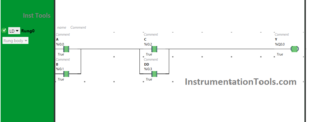
PLC Programming on Logic Circuit

When Input A, Input B Input C, and Input D, all are turned ON, the output Y (Q0.0) will be ON. Turning ON all the inputs will not turn OFF the output Y (Q0.0).

If you liked this article, please subscribe to our YouTube Channel for PLC and SCADA video tutorials.

You can also follow us on Facebook and Twitter to receive daily updates.

Read Next:

  • PLC Motor Logic with Pushbuttons
  • Basic PLC Alarm Programming Example
  • Compare CompactLogix and ControlLogix
  • Standard 4 to 20 mA Conversion Formula
  • Start Stop of one Motor PLC program
Don't Miss Our Updates
Be the first to get exclusive content straight to your email.
We promise not to spam you. You can unsubscribe at any time.
Invalid email address
You've successfully subscribed !
Mis-conceptions of PLC Ladder Logic
Conveyor Speed Logic using Structured Text in PLC
How is Data Stored in Standard Modbus Protocol?
Your First Steps Through STL Language
Free Schneider PLC Training – Automation Course
Share This Article
Facebook Whatsapp Whatsapp LinkedIn Copy Link
Share
Leave a Comment

Leave a Reply Cancel reply

Your email address will not be published. Required fields are marked *

Stay Connected

128.3kFollowersLike
69.1kFollowersFollow
208kSubscribersSubscribe
38kFollowersFollow

Categories

Recent Comments

  • Kamli on Top Free PLC Software
  • Guifty Shimica on Top Non-PLC Certification Courses for Automation Professionals
  • Guifty Shimica on Top Non-PLC Certification Courses for Automation Professionals
  • MIHARITSOA Aina Sitraka on Top Non-PLC Certification Courses for Automation Professionals

Related Articles

Advanced Ladder Logic PLC Example

Automatic Sanitizer – Complex Ladder Logic PLC Examples

Types of Digital Outputs in PLC

Types of Digital Outputs in PLC

Check Block Consistency Tools

Check Block Consistency Tools in Simatic Manager

Omron PLC Online Training Course

Omron PLC Online Training Course

Introduction to GOC controllers

Mitsubishi Electric GOC Controllers

Pulse Generation using Timer in Siemens PLC

Pulse Generation using Timer in Siemens PLC

PLC Program for Blinking Lamp on 5 Seconds Interval

PLC Program for Blinking Lamp on 5 Seconds Interval

Simple Conveyor Control PLC Program

XG5000 Example of Simple Conveyor Control PLC Program

More Articles

Carbon Monoxide Gas Detector

Carbon Monoxide Gas Sensor Principle

Addressable Fire Alarm System

Which One is Best – Conventional or Addressable Fire Alarm System?

Combining Independent Voltage Sources in Series

Combining Independent Voltage Sources in Series

Allen Bradley PLC Emulator

How to Work with Allen Bradley RsLogix Emulator?

Traffic Lights Ladder Diagram using Timers

Traffic Lights Ladder Diagram using Timers

Hazards of Compressed Air

Hazards of Compressed Air

Difference between Orifice & Restriction Orifice

psv-principle-of-operation

Instrumentation Inspection Report

Follow US
All rights reserved. Reproduction in whole or in part without written permission is prohibited.
Welcome Back!

Sign in to your account

Username or Email Address
Password

Lost your password?