Inst ToolsInst ToolsInst Tools
  • Courses
  • Automation
    • PLC
    • Control System
    • Safety System
    • Communication
    • Fire & Gas System
  • Instrumentation
    • Design
    • Pressure
    • Temperature
    • Flow
    • Level
    • Vibration
    • Analyzer
    • Control Valve
    • Switch
    • Calibration
    • Erection & Commissioning
  • Interview
    • Instrumentation
    • Electrical
    • Electronics
    • Practical
  • Q&A
    • Instrumentation
    • Control System
    • Electrical
    • Electronics
    • Analog Electronics
    • Digital Electronics
    • Power Electronics
    • Microprocessor
  • Request
Search
  • Books
  • Software
  • Projects
  • Process
  • Tools
  • Basics
  • Formula
  • Power Plant
  • Root Cause Analysis
  • Electrical Basics
  • Animation
  • Standards
  • 4-20 mA Course
  • Siemens PLC Course
Reading: PLC Interlock Logic with First Input Priority
Share
Notification Show More
Font ResizerAa
Inst ToolsInst Tools
Font ResizerAa
  • Courses
  • Design
  • PLC
  • Interview
  • Control System
Search
  • Courses
  • Automation
    • PLC
    • Control System
    • Safety System
    • Communication
    • Fire & Gas System
  • Instrumentation
    • Design
    • Pressure
    • Temperature
    • Flow
    • Level
    • Vibration
    • Analyzer
    • Control Valve
    • Switch
    • Calibration
    • Erection & Commissioning
  • Interview
    • Instrumentation
    • Electrical
    • Electronics
    • Practical
  • Q&A
    • Instrumentation
    • Control System
    • Electrical
    • Electronics
    • Analog Electronics
    • Digital Electronics
    • Power Electronics
    • Microprocessor
  • Request
Follow US
All rights reserved. Reproduction in whole or in part without written permission is prohibited.
Inst Tools > Blog > PLC Tutorials > PLC Interlock Logic with First Input Priority

PLC Interlock Logic with First Input Priority

The PLC interlock logic is used to provide priority to the input first operated to avoid any damage to the equipment and machines.

Last updated: October 17, 2023 1:58 pm
Editorial Staff
PLC Tutorials
No Comments
Share
6 Min Read
SHARE

In Industrial process control, we need different types of interlock logic to achieve the desired control and trip functions as per the requirements.

Contents
PLC Interlock ExampleMotor Forward and Reverse PLC Logic without InterlockInterlock Logic with First Input PriorityMotor Forward DirectionMotor Reverse DirectionPLC Interlock Video Tutorial

The PLC interlock logic is used to provide priority to the input first operated to avoid any damage to the equipment and machines or to avoid any undesired interruption.

One of the logic is interlock with first input priority. Say we have a machine that can do 5 different types of functions. We have 5 different types of inputs available to control the machine operation but the machine will do only one function at a time as per the selected input.

If input 1 is selected then the machine will do function 1. Similarly, if input 2 is given to the machine then the machine will do function 2 and so on. Be careful that the machine may be damaged if two or more inputs are given at the same time.

Here in this case we need to write a PLC interlock logic such that whatever the first selected input has high priority. Meanwhile, if any other input is given to the machine then it has to disregard the other input until the present operation completes.

PLC Interlock Example

Consider a motor that can operate in two directions as per the operator selection.

The motor can rotate in the forward direction or in the reverse direction. But the motor can rotate in only one direction at a time.

If we give both forward or reverse commands at the same time then the motor will be damaged.

PLC Interlock Example

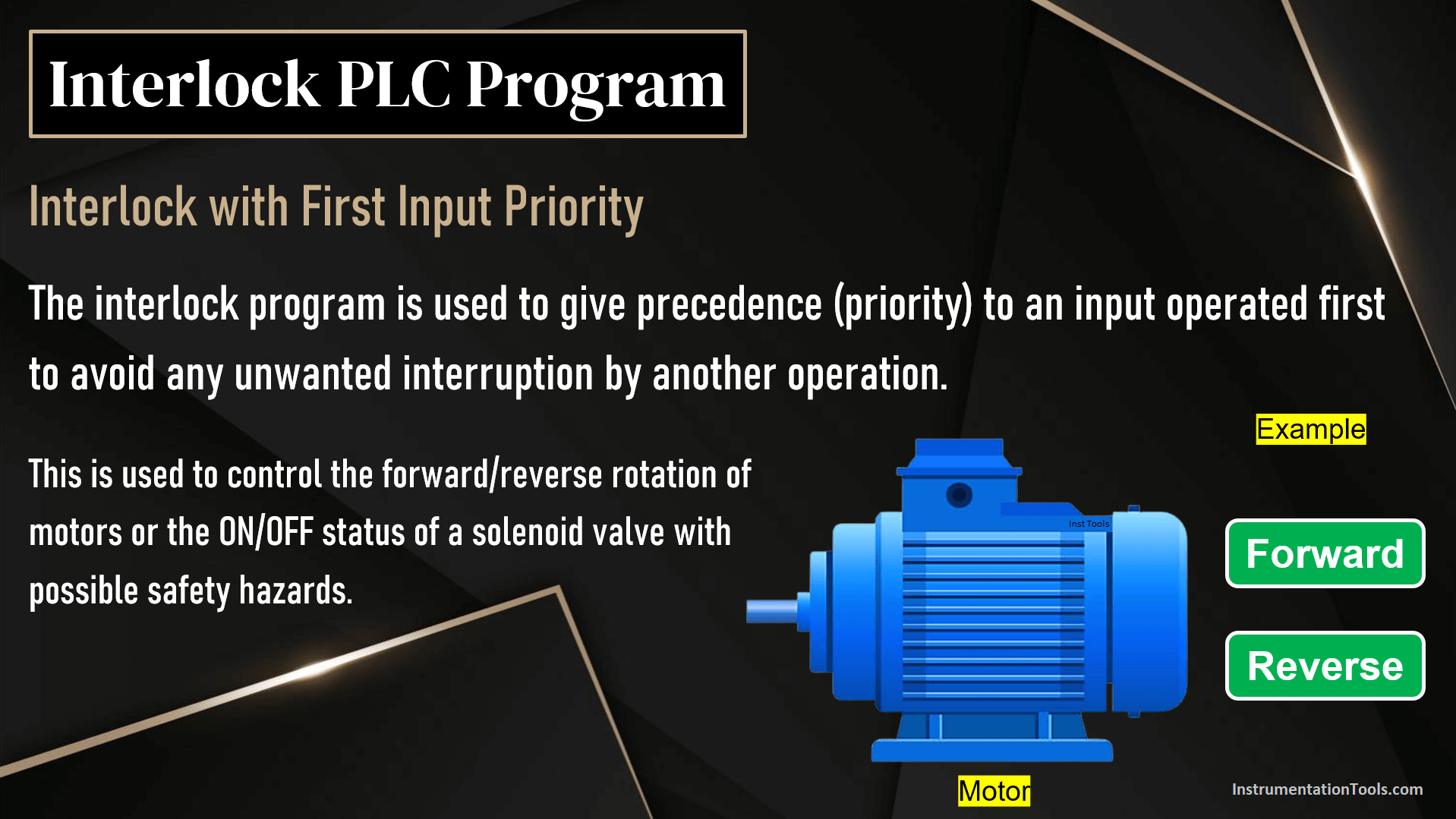
The operator can start the motor in the forward direction using a Forward selector switch and similarly, the operator can start the motor in the reverse direction using a Reverse selector switch.

Motor Forward and Reverse PLC Logic without Interlock

In general, the motor logics are equipped with many safety functions and other motor-related pushbuttons like start, stop, and emergency stop.

Here in this article, we are just focusing on simple forward and reverse logic for understanding the interlock program.

Motor Forward and Reverse PLC Logic without Interlock

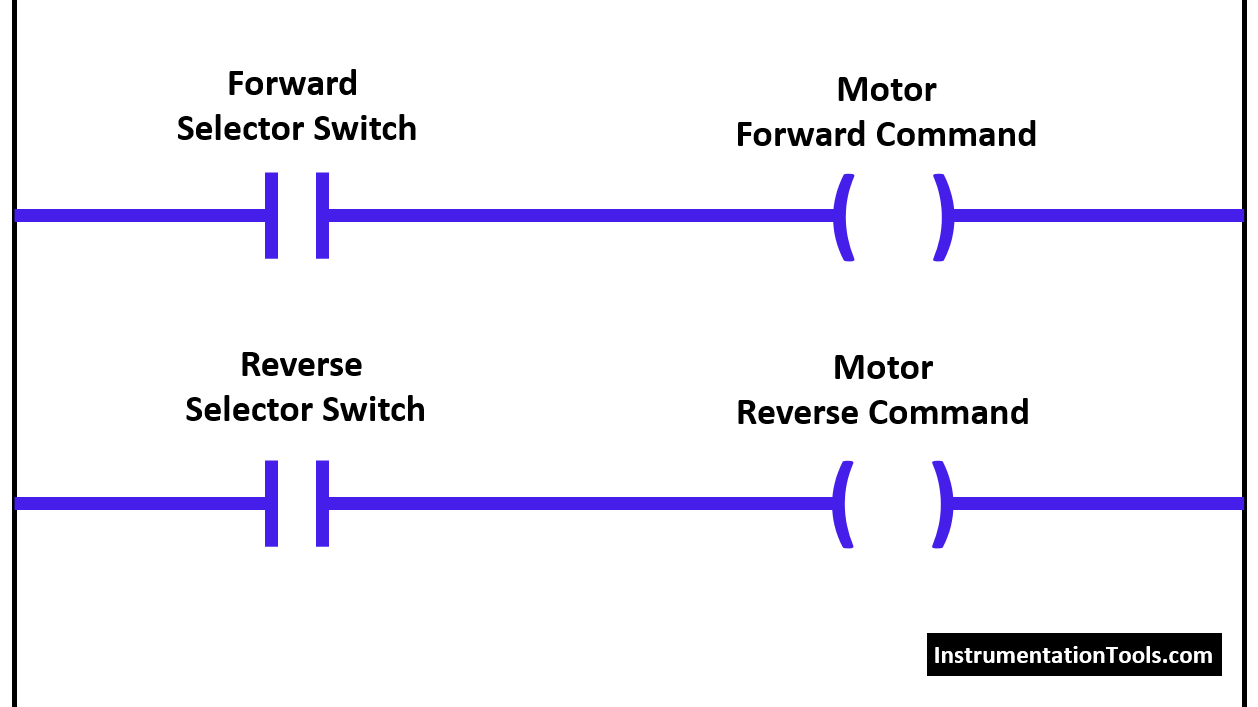
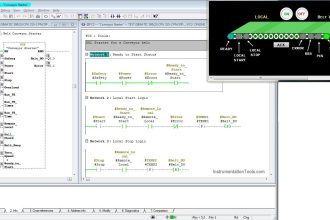
In the above PLC logic, when the forward selector switch is ON then the motor forward command will be initiated. Similarly, if the reverse selector switch is ON then the motor reverse command will be initiated.

In this logic, if both forward selector switch and reverse selector switch are ON at the same time then both forward and reverse commands will be initiated and these types of logic/situations damage the motors or any other machines.

Interlock Logic with First Input Priority

Now we can avoid these problems with help of an interlock program. This program is called Interlock with the first input priority.

We have to insert the Normally-Close (N.C.) status of motor output commands in the input side to implement this interlock logic.

Insert N.C. status of motor reverse command with the motor forward selector switch as shown in the below figure.

Again insert N.C. status of motor reverse command with the motor reverse selection switch as shown in the below figure.

PLC Interlock Logic with First Input Priority

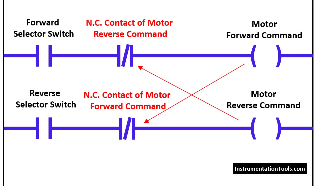
Initially, the motor will be in an OFF state so both N.C. contacts are in a close state.

Motor Forward Direction

Say if the operator started the motor in a forward direction then the N.C. contact of the motor forward command will be open in the second rung.

During this time, even if the operator activates the reverse selector switch then this command will not be initiated because N.C. contact is activated and it is open when the motor running in the forward direction.

Motor Reverse Direction

Similarly, if the operator started the motor in a reverse direction then the N.C. contact of the motor reverse command will be open in the first rung.

During this time, even if the operator activates the forward selector switch then this command will not be initiated because N.C. contact is activated and it is open when the motor running in reverse direction.

PLC Interlock Video Tutorial

In this video, I explained the importance of interlock logic with the first input priority.

If you liked this article, then please subscribe to our YouTube Channel for PLC and SCADA video tutorials.

You can also follow us on Facebook and Twitter to receive daily updates.

Read Next

  • PLC Tanks Filling as per Priority
  • Selector Control Functions
  • Basics of Trips and Interlocks
  • PLC Conveyors with Interlock
  • Permissive and Interlock Circuits
Don't Miss Our Updates
Be the first to get exclusive content straight to your email.
We promise not to spam you. You can unsubscribe at any time.
Invalid email address
You've successfully subscribed !

Continue Reading

What is Nest Loading? – DCS and PLC Control Systems
Basics of Permissive and Interlock Circuits
PID Block in RSLogix 500
#18 PLC Best Practices – Store PLC Hard Stop Events from Faults
Programmable Logic Controller (PLC) Scan Time – Types, Theory
How to Blink Lights in Ladder Logic?
Share This Article
Facebook Whatsapp Whatsapp LinkedIn Copy Link
Share
Leave a Comment

Leave a Reply Cancel reply

Your email address will not be published. Required fields are marked *

Stay Connected

128.3kFollowersLike
69.1kFollowersFollow
210kSubscribersSubscribe
38kFollowersFollow

Categories

Explore More

Down Counter PLC Program
PLC Structured Text Program for Light Sequences via Timers
PLC Example with Switches
Distributed IO Sharing Between PLC Systems – Technical Insights
Motor ON OFF Logic in PLC
Normally-Closed Contacts for Stop Buttons
Network Switch Port Allocation Details
Control Two Motors in Sequence after Time Delay – Circuit, Operation

Keep Learning

PLC Sequential Lights Control Example

PLC Timer Example: Sequential Control of Three Lights with Reset

Top Non-PLC Certification Courses for Automation Professionals

Top Non-PLC Certification Courses for Automation Professionals

PLC Program to Control Level of Two Tanks

PLC Level Control of Two Tanks

Global Data Blocks in PLC

What is a Data Block? Global Data Blocks in PLC

Allen Bradley SLC 500 PLC Programming

PLC Sequence Programming Ladder Logic

PLC Sequence Programming Ladder Logic

PLC Temperature Control using Pulse Width Modulation

PLC Temperature Control using Pulse Width Modulation (PWM)

PLC Scan Time

PLC Scan Time

Learn More

Master Control Reset (MCR) ladder logic

How to use Master Control Reset (MCR) Instruction in PLC

TON Timer in RSlogix

Why is RTO used in the Place of TON Timer?

Pneumatic-Level-Transmitter-Value-Struck

Pneumatic Level Transmitter Value Struck?

Pneumatic and Hydraulic Projects

200 Pneumatic and Hydraulic Projects List

Emergency ShutDown Valve Working Principle

ESDV : How it Works ?

Tank Level Control Process in PLC

Tank Level Control in PLC

Pressure Gauges Common Problems

Pressure Gauges : Common Causes for Failures and Their Effective Solutions

Digital Electronics Multiple Choice Questions

Multivibrators Objective Questions

Menu

  • About
  • Privacy Policy
  • Copyright

Quick Links

  • Learn PLC
  • Helping Hand
  • Part Time Job

YouTube Subscribe

Follow US
All rights reserved. Reproduction in whole or in part without written permission is prohibited.
Welcome Back!

Sign in to your account

Username or Email Address
Password

Lost your password?