In this article, you will learn the PLC example to control LEDs via switches and understand the ladder logic explanation.
This PLC example is designed for engineering students to learn and practice the ladder logic. The implementation of the same PLC program for industrial usage will be different.
PLC Example
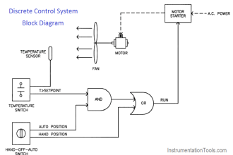
Design a PLC ladder logic for the following application.
We are using three switches to control three LED’s.
If any 1 Switch is ON, then LED I will be ON.
If any 2 Switches are ON, then LED II will be ON.
If all the 3 Switches are ON, then LED III will be ON.
In the previous article, we discussed the same PLC example using toggle switches, Learn the logic.
Inputs
The required digital inputs are listed below.
Switch 1: I0.0
Switch 2: I0.1
Switch 3: I0.2
Outputs
The required digital outputs are listed below.
Motor 1: Q0.0
Motor 2: Q0.1
Motor 3: Q0.2
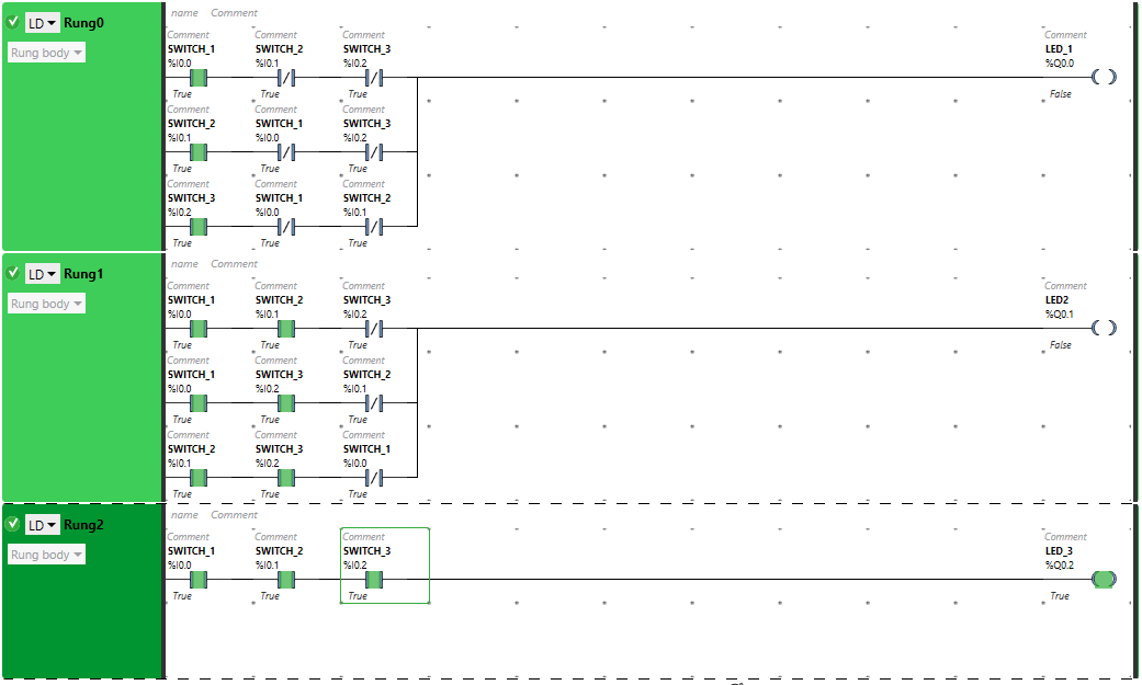
Ladder Diagram to Control LEDs Via Switches
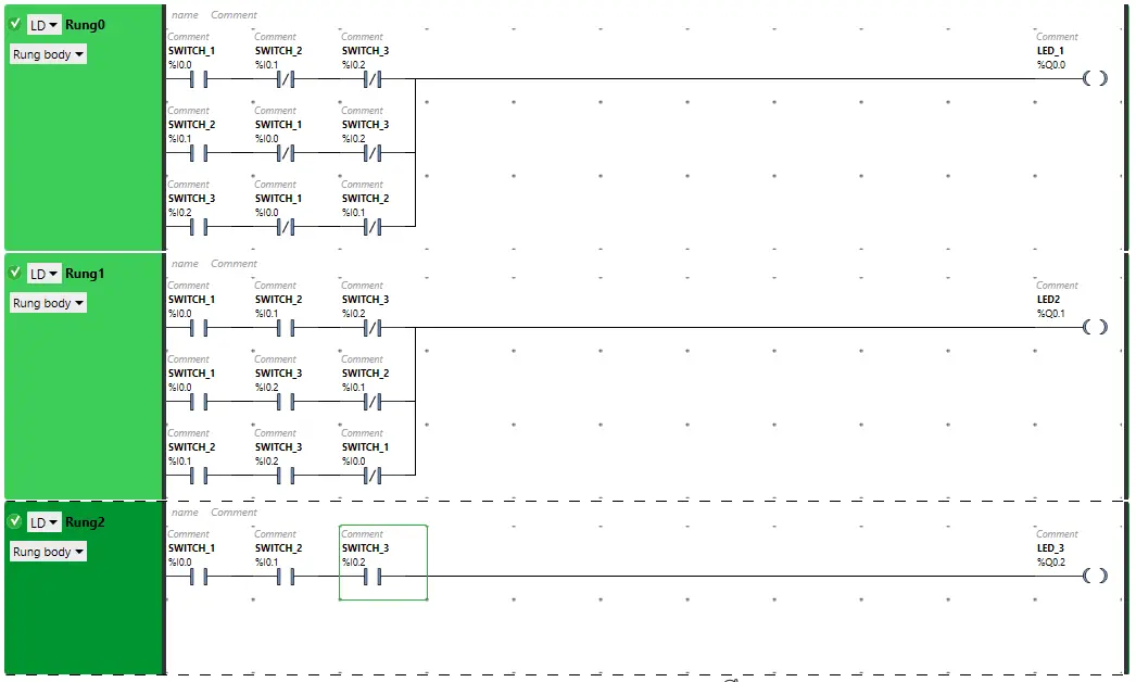
Ladder Logic Explanation
- For this application, we have used EcoStruxure Machine Expert Basic v1.2 software for the PLC programming.
- In the above program, we have used Normally Open Contacts as well as Normally Closed Contacts for Switch 1 (I0.0), Switch 2 (I0.1), and Switch 3 (I0.2)
- In Rung0, when any 1 switch (Normally Copen Contact) is turned ON and the other 2 switches (Normally Closed Contacts) are OFF, then LED 1 will turn ON.
- To turn ON LED 2 Rung1, any 2 switches that are as Normally Open Contacts should be ON and the other remaining 1 switch as Normally Closed Contact should be OFF.
- For LED 3 to be ON, switch 1, switch 2 and switch 3 in Rung2 are connected in series, thus implementing AND logic gate.
- LED 3 will TURN ON when all the three switches are turned ON.
When Any 1 Switch is ON
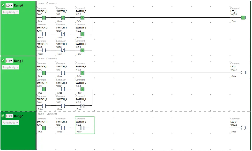
The signal flows through switch 1 as it is in true state. In false state, switch 2 and switch 3 also pass signal to the outputs. Therefore, LED 1 will be ON.
LED I will TURN ON when switch 2 is turned ON and switch 1 and switch 3 are OFF as these are in normally closed contact state.
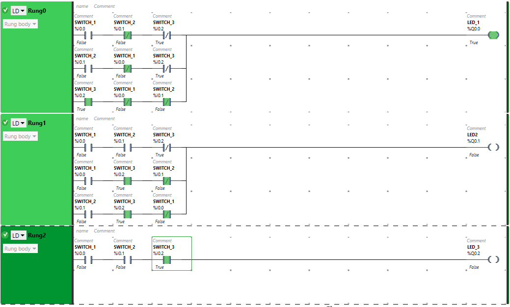
When switch 3 will be ON and other 2 switches which are normally closed contacts will be OFF, then LED 1 will turn ON.
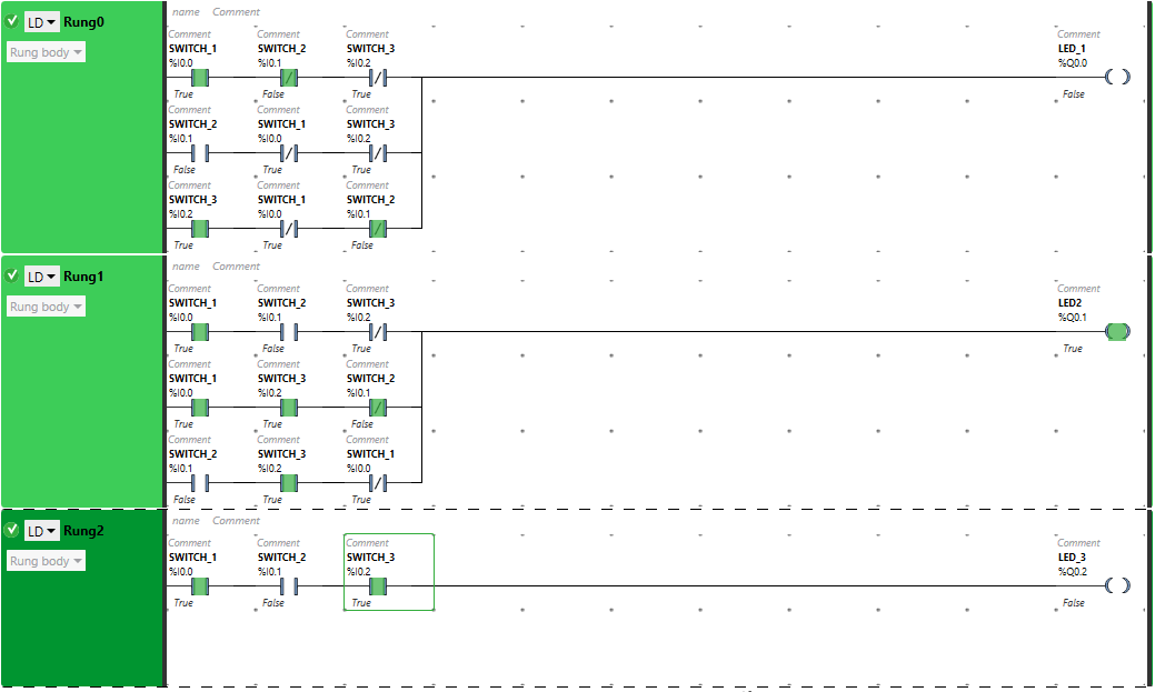
Turning ON more than one switch will break the circuit. The Normally Closed Contact, when in true state, will not allow signal. As a result, LED 1 will be OFF.
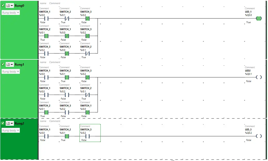
When Any 2 Switches are ON
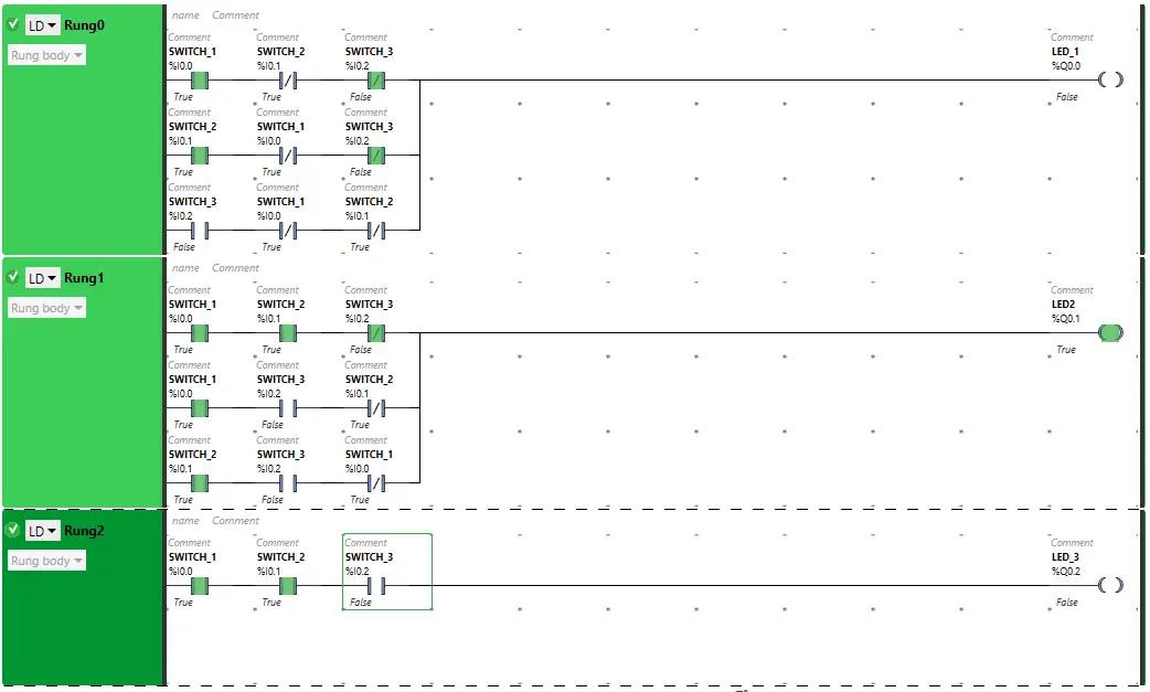
LED 2 will TURN ON when switch 1, switch 2 are turned ON and Switch 3 is OFF. The switch 3 as Normally Closed Contact, in false state, will allow signal to pass through it.
When switch 1 and switch 3 are turned ON and switch 2 is OFF, LED 2 will turn ON. Switch 2 will allow signal when in false state.
The signal flows through switch 2 and switch 3 as these are in true state. In false state, switch 1 also pass signal to the outputs. Therefore, LED 2 will be ON.
When more than two inputs are turned ON, the Normally Closed Contact used for the third switch will not close the circuit in true state. Therefore, the LED 2 will get OFF.
When All 3 Switches are ON
When all the three switches SWITCH 1 (I0.0), SWITCH 2 (I0.1), SWITCH 3 (I0.2) are turned ON, LED 3 will be ON and will turn OFF other Two outputs.
PLC Example Video
We explained this PLC example program in the below video. Watch and learn the ladder logic.
If you liked this article, then please subscribe to our YouTube Channel for PLC and SCADA video tutorials.
You can also follow us on Facebook and Twitter to receive daily updates.
Read Next:
- Free Schneider PLC Training
- Real-time PLC Automation Projects
- How to Choose a PLC for a Project?
- Moving Data between Siemens PLCs
- Siemens Communication using I-Device