There are a number of points to consider in a pressure measurement application. All require some thought in both the planning and execution.
Location of Process Connections
Process connections should be located on the top of the process line for gases, and on the side of the lines for other fluids.
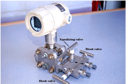
Isolation Valves
Many pressure devices require tapping points into the process. Isolation valves should be considered between the process fluid and the measuring equipment if the device is required to be taken out of service for replacement or calibration.
Use of Impulse Tubing
Impulse piping should be as short as possible. Instruments in gas applications should be self draining. Self draining can be achieved by sloping the lines towards the process to avoid trapping condensables and liquids.
Instruments used in liquid and condensable applications should be self-venting. Self-venting is performed by sloping the lines towards the instrument to avoid trapping gas.
If solids can accumulate in the impulse line, tees and plug fittings should be installed in the place of elbows to allow for “rodding” of plugged lines.
Test And Drain Valves
Apart from the isolation valve at the process connection, the need for test and drain valves must be evaluated. If the fluid to be measured is toxic or corrosive, a blowdown valve line should be provided.
For maintenance reasons, all valves must be accessible from either the ground or suitable platforms.
Sensor Construction
Depending on the environment in which the instrument is to be used, selection of the correct sensor should also involve physical conditions. The sensor may need to be isolated mechanically, electronically and thermally from the process medium and the external environment.
Mechanical and thermal isolation can be achieved by moving the sensor away from the process flange to a position in the neck of the electronics housing. Designs of this type relieve mechanical stress on the cell. This can result in improved static pressure performance and removes the sensor from direct heat.
Glass-sealed pressure transport tubes and insulated cell mountings provide electrical isolation. This improves performance and provides transient protection for the electronics.
Temperature Effects
High temperatures and large temperature variations can affect pressure measuring equipment.
One of the most common forms of temperature compensation is to use a Wheatstone bridge. Apart from the primary sensor, a dummy sensor is used which is not subjected to the forces but is also affected by temperature variations. In the bridge arrangement the dummy sensor cancels the primary sensor’s voltage and thus eliminates temperature variations in the measurement.
Temperature measurement and correction within the device is another form of compensation for thermal effects, but is the more expensive choice.
Remote Diaphragm Seals
Remote diaphragm seals can be used to prevent the process medium from contacting the transmitter diaphragm while measuring process pressure.
Remote seal systems should be considered if:
- corrosion may cause a problem to the transmitter and pressure sensing element.
- the sensing fluid contains suspended solids or is sufficiently viscous to clog the piping.
- the process temperature is outside of the normal operating range of the transmitter.
- the process fluid may freeze or solidify in the transmitter or impulse piping.
- the process medium needs to be flushed out of the process connections when changing batches.
- maintaining sanitary or aseptic conditions.
- eliminating the maintenance required with wet leg applications.
- making density or other measurements.
Precautions With Remote Diaphragm Seals
Although the benefits of using remote diaphragm seals are listed above, they can however have an effect on the overall transmitter response. By selecting the correct seals, capillaries and fill fluid, the effects of transmitter performance can be minimised while still achieving process requirements.
The following points can assist when selecting the different parts of a remote seal system:
- Larger diameter diaphragms minimise the temperature effects that are common with remote seals.
- Minimising the length of the capillary reduces temperature effects and also improves response time.
- In a two-seal system, the same diaphragm size, capillary length and fill fluid should be used on each side of the transmitter.
- Mount the transmitter at or below the lower tap for vacuum applications. Capillary length may be an inhibiting factor.
- The fill fluid should be selected to perform in the most extreme process conditions. The two critical criteria being highest temperature and lowest pressure.
- Select a fill fluid that is compatible with the process fluid, in case of contamination.
Process Flanges
- Coplanar flange
These are becoming more standard for newer pressure transmitters. They are generally small and lightweight which makes for easier installation. They have a process operating temperature up to 120oC.
- Traditional flange
These are used in installations that require traditional biplanar configurations. An increased operating temperature at process connections, up to 150oC is possible.
- Level flange
This permits direct process mounting and is of a simple construction and low cost.
Additional Hardware
If pulsation dampeners are required, the materials and fill fluid must be compatible with the process fluid being measured. In addition, siphons of the correct material are required for all vapours above 60oC, where condensation will occur.
If diaphragm seals are required, a flushing connection requirement must be assessed.
Impact on the Overall Control Loop
Sensing devices that are situated in a control loop generally have an effect when the range of operation or response time changes.
With pressure measurement devices, problems occur due to:
- Material build-up on the sensing element causing a longer response
- Overranging causing incorrect readings


Thanks for Tips, are really useful, please continue doing this good job “Teach Instrumentation”, and congratulation for this marvelous web site.
good post thanks please i have just questions about installation for pressure transmitter and DPT also flow ( DPT) when we use condensatepot ? in wish temperature and pressure is there any standard ?
and also for installation of pressure transmiter in case of steam and vapor the hook up drawing it’s differenti mean have different tapping point ?
What is the correct tube installation for a Pressure Transmitter in gas service in which the sensing point is located on top/center of horizontal Gas Separator? Also, since the instrument is mounted on the stand below the tap location, is there a need to also install a drip pot?
And if it does require a drip pot. At what location in the tube install should the pot be installed. My guess is that the Drip pot should be located off of the Press. tap and before the tube enters the transmitter manifold.
I realize that direct mounting to the sensing tap would have probably been preferable, but the device was installed on Inst. stand below the sensing tap. All tips/video tutorials, and advice would be greatly appreciated in helping out this Instrument construction foreman with this issue.