In this article, I will show you how to monitor and modify variables from the hardware configuration using the Siemens Simatic manager.
Monitor and Modify Variables
Follow the below steps to monitor and modify variables from the hardware configuration.
Step 1:
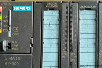
Open Simatic manager. Select the “CPU” and double click on “hardware” to enter in to hardware environment.
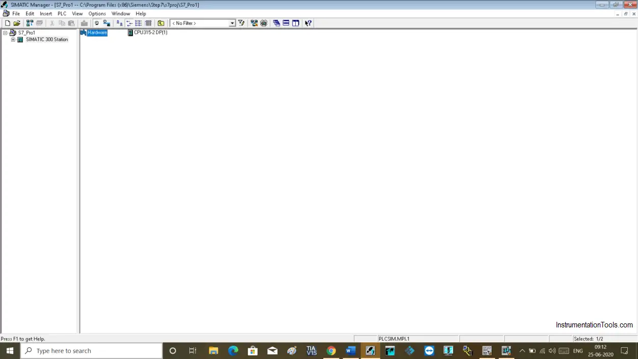
Step 2:
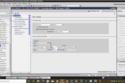
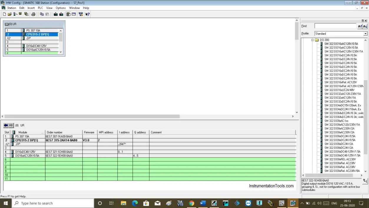
The following hardware configuration window will open up.
Step 3:
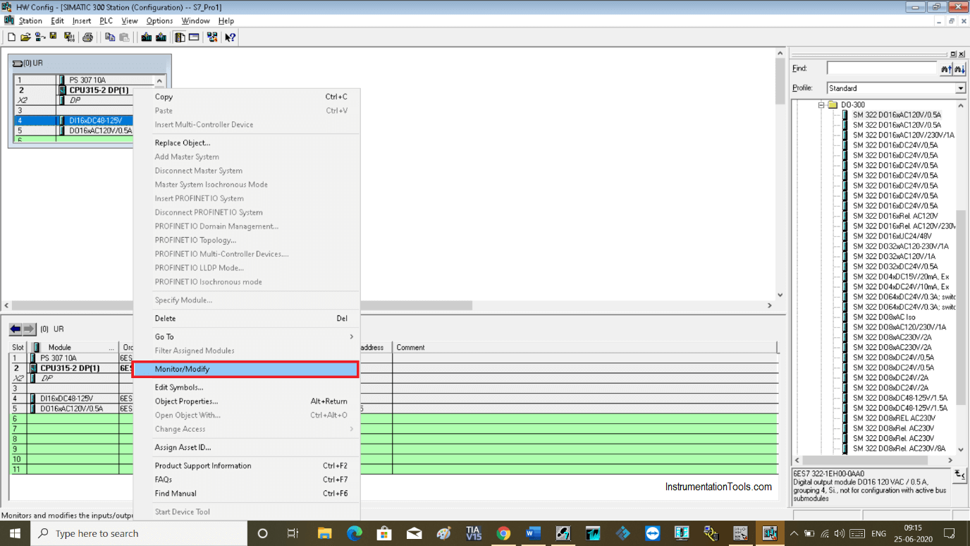
To monitor or modify a variable, select digital input or output card and do right-click to open properties as you can see in the below window.
Click on monitor/modify to open a new window.
To monitor or modify a variable, download project to the simulator.
Step 4:
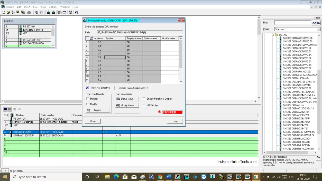
The following window will open up. Here, as I have selected digital inputs, it will only show digital inputs.
Step 5:
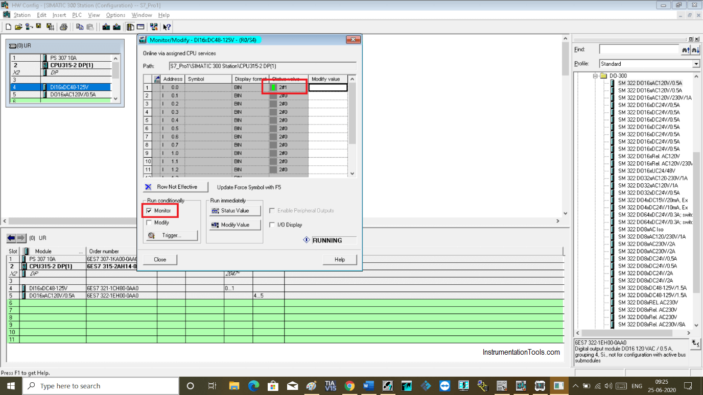
To monitor the input variable, do checkmark as shown in the below window.
Keep the program in monitor mode to see the status of the input variable.
Step 6:
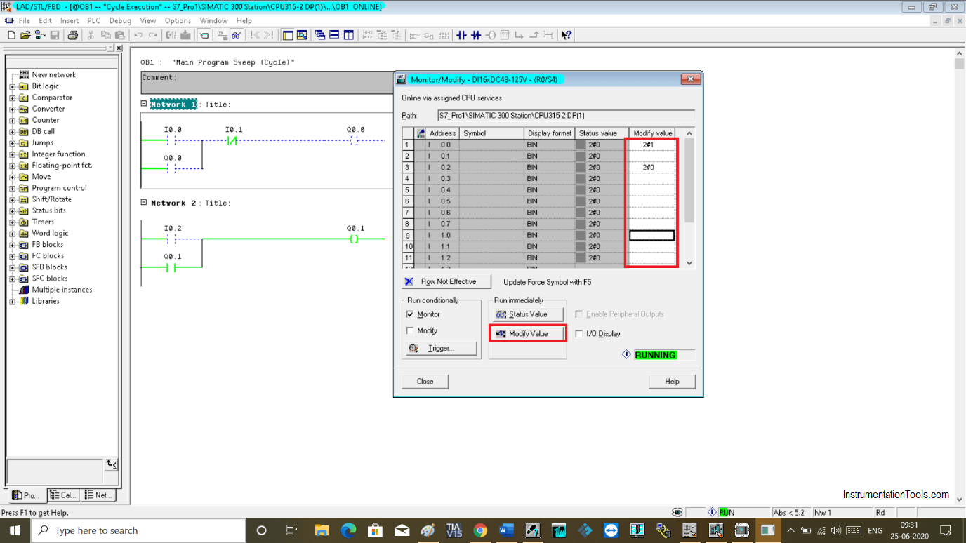
Now to modify the value or to change the status of the input variable, use the modify option.
To modify a value, click on modify value and write “0” or “1” then click on “modify value” to make changes.
Step 7:
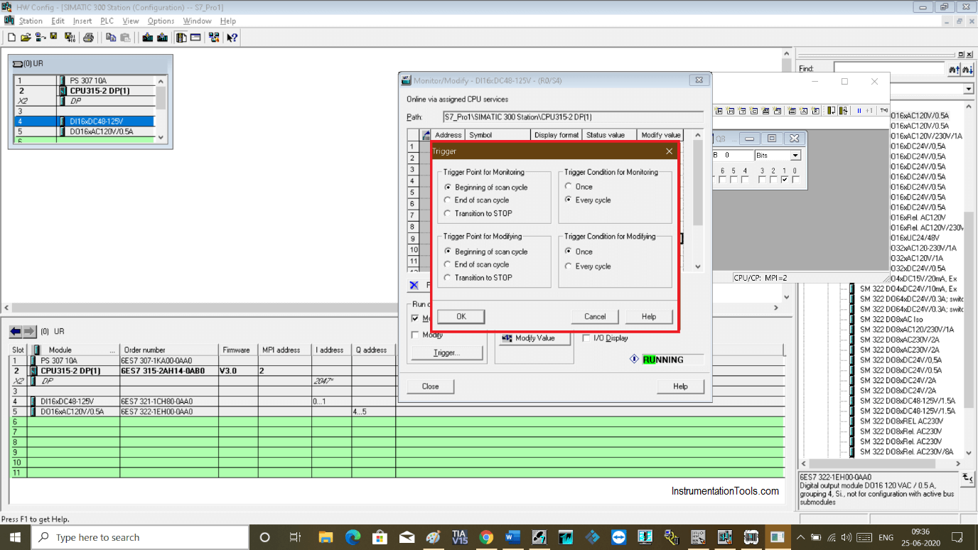
Under modify and monitor option, there is one more tab “ trigger” is available.
Clicking on the trigger will open up a new window.
Here, as you can see triggering options for modifying and monitoring value.
You can set it as per your requirement for a single scan cycle or every scan cycle.
Author: Suhel Patel
If you liked this article, then please subscribe to our YouTube Channel for PLC and SCADA video tutorials.
You can also follow us on Facebook and Twitter to receive daily updates.
Read Next:
- RSLogix 500 PID Instruction
- Siemens S7 300 CPU Status
- Rewire Tool in Simatic Manager
- Trace Function in Tia Portal
- Simatic Manager New Project