Today Modbus is a very widely used communication protocol in industrial automation. Be it any sensor or some other type of field instrument, this protocol is being employed in them too for efficient data transfer. And because data plays a very important role nowadays, bulk information is required and for that, Modbus is one of the most preferred protocols for programmers.
When a programmer is working on this protocol, he must know how to use it in a design for a network system. In this post, we will see how Modbus is used in industrial networks.
What is Modbus?
Modbus is a communication protocol used in industrial automation systems. Modbus is basically a messaging structure which has data (predefined and variable) in its own format. Modbus works on master-slave architecture. This means, that for communication through Modbus, one device must be a master and the other must be a slave. Then only, data exchange can happen.
A request is first sent by the master and based on that, the slave responds by sending data. The message contains the following format – address of slave, command type (read or write), data, and checksum error code.
Modbus is an open protocol and is employed by many vendors worldwide in their products. One thing to remember is that Modbus is a serial communication.
Modbus communication protocol in industrial automation
To understand how Modbus is used in industrial networks, let us now refer the following points:
Modbus works in three physical layers – RS232, RS422 and RS485. In RS232, you can have only one master and one slave; whereas, in RS422 and RS485, you can have multiple slaves with a single master. And out of RS422 and RS485, RS485 is the most used one as RS422 faces issues in design of multi-point communication.
As discussed earlier, a Modbus message consists of read or write instruction. And in it’s language, it is called a function code. The following function codes are used in Modbus as shown in the below image. It basically specifies what type of data to read or write and what will be the maximum length of data that can be exchanged.
This provides an easy way to communicate with devices. When communicating, a programmer must specify the function code in his program before establishing communication. Then only, the Modbus port of the master will identify what type of action to do on it’s slaves.
| Function Code | Name | Description |
| 0 | 0 | No address information is present |
| 1 | Read Coils | Read the status of discrete coils in a device |
| 2 | Read Discrete Inputs | Read the status of input registers in a device |
| 3 | Read Multiple Registers | Read the status of multiple holding registers in a device |
| 16 | Write Multiple Registers | Write a series of holding registers in a device |
| 4 | Read Input Registers | Read the status of multiple input registers in a device |
| 5 | Write Single Coil | Write a single coil in a device |
| 6 | Write Single Register | Write a single register in a device |
| 7 | Read Exception Status | Read information about the last exception |
| 15 | Write Multiple Coils | Can be used to set multiple coil values in a single go |
| 20 | Read File Record | Read a file record information |
| 21 | Write File Record | Write a file record information |
| 22 | Mask Write Register | Write a holding register after applying AND & OR masks |
| 23 | Read/Write Multiple Registers | Performs a write after read operation |
| 24 | Read FIFO | Reads from the device FIFO |
| 43 | Read Device Information | Fetch information about the device including vendor name, product code, versions, etc. |
Modbus uses three types of variations for communication – RTU, ASCII and TCP/IP. RTU and TCP/IP use binary coding and CRC error checking. But, RTU works on serial physical layer (2-wire, 3-wire or 9-wire) and TCP/IP works on Ethernet physical layer. ASCII uses ASCII characters to begin and end messages.
A Modbus port can be used only as a master or slave at a time. They cannot be bi-functional. Suppose a PLC is a master, and a VFD is a slave (because VFD has data and PLC needs data). Always remember that the one who requires data is the master. So, in PLC programming, you have to configure the PLC port as master (as VFD is slave by default and it cannot be master).
Modbus RTU has the following settings – baud rate, parity, stop bit and data length; whereas in Modbus TCP IP, you just have to enter the IP address and device ID.
Modbus theoretically works at a distance of maximum of 4000 feet, but practically, due to electrical noise in the panel or cable conduits, noise interferes and the distance drops to 1000 feet. After that, programmers mostly face issues in signal delay or even lack of communication. So, if the distance is larger, you have to install repeaters or amplifiers at every certain distance. This boosts the signal and helps in longer distance connectivity.
For effective performance, an earthing point must be connected in the Modbus port connectivity, along with the regular wiring or connector. This reduces noise to a great extent, as Modbus is somehow more prone to electrical noise interference.
When you are programming in PLC for Modbus communication, the read or write communication blocks must be executed one by one, and not simultaneously. This is because Modbus communication cannot execute multiple functions at a time.
Modbus in Industrial Networks
Let us use a simple Modbus example and understand by the below drawing. As seen, there are 4 devices – 2 VFD’s, one PLC and one SCADA system.
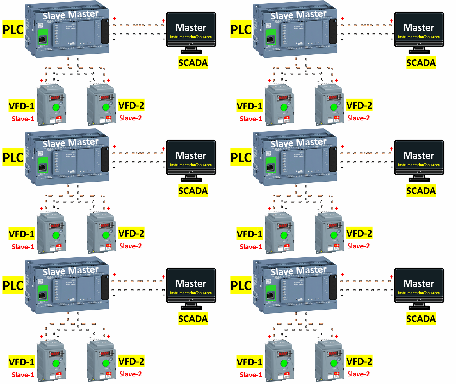
The PLC has two Modbus ports, so one must be configured as a master for VFDs, and the other must be configured as a slave for the SCADA system. The two VFDs are looped together in the wiring in a daisy chain configuration. Then, they are brought together in a single PLC Modbus port, configured as a master.
Here, programming will be done to read or write data with respect to the individual VFD (these codes will be executed one by one). Now, SCADA wants this data from the PLC. So, the other port of PLC will be used as a slave and SCADA will fetch data from that (so ultimately, VFD data is sent to the SCADA through PLC).
This type of configuration must be done and care must be taken to ensure proper addresses are assigned to the slave devices (they should not clash with the same addresses).
The voltage in the electrical panel between neutral and earthing must be less than 0.5V for noise elimination and reduced signal disturbance for Modbus channels.
In this way, we saw how to implement Modbus in industrial networks.
Read Next:
- Introduction to Modbus Reading Writing
- How Modbus Communication works
- Modbus Function Codes and Addresses
- Motor Control using Modbus Communication
- Modbus Communication Interview Questions



Please send to New mail