This article will discuss the use of the Counter instruction in the GX-Works2 Mitsubishi PLC software. It is used to count the number of events or occurrences that happen within a program. In this program, the Counter and Increment/Decrement instructions will be used to activate specific outputs.
Program Objective
COUNTER Instruction
This counter instruction is an upward-counting type of counter instruction.
This instruction counts events and stores the value in a counter memory (e.g., C0). The CNT instruction has one input parameter to increment the counter’s present value (PV). The counter’s PV can only be reset using the Reset (RST) instruction with the same counter memory address. Numeric values in GX-Works software must be written with the prefix “K”.
In this instruction, the counter’s set value (SV) is set to 5 (K5), and it will activate Output 1 after receiving 5 trigger signals.
INCREMENT (INC) and DECREMENT (DEC) Instructions
The INC and DEC instructions are used to increase or decrease the value stored in a word memory, functioning similarly to a reversible counter.
These instructions store the counted value in word memory (e.g., D0). Both INC and DEC instructions have one input parameter used to increase or decrease the value. In this program, the word memory value is combined with comparison instructions (=, >, <).
Each comparison instruction has its own set value (SV) parameter and will be used to activate an output.
Mitsubishi Counter Programming Using Ladder Diagram
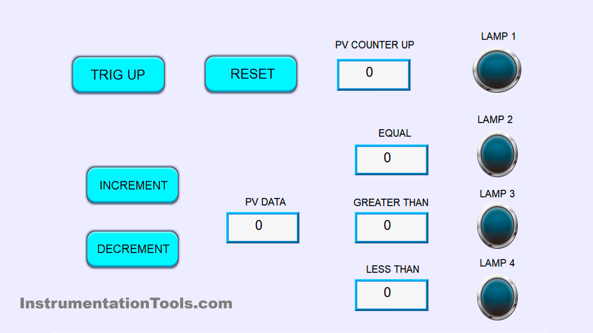
Simulation Video
In the video below, we showed you the Mitsubishi counters program simulation in GX-Works2.
IO Mapping
| S.No. | Comment | Input | Output | Counter | Memory Word |
|---|---|---|---|---|---|
| 1 | TRIGGER COUNTER | M1000 | |||
| 2 | TRIGGER RESET | M1001 | |||
| 3 | TRIGGER INC | M1002 | |||
| 4 | TRIGGER DEC | M1003 | |||
| 5 | Y001 | OUT 1 | |||
| 6 | Y002 | OUT 2 | |||
| 7 | Y003 | OUT 3 | |||
| 8 | Y001 | OUT 4 | |||
| 9 | COUNTER UP | C0 | |||
| 10 | DATA | D0 | |||
| 11 | SV EQUAL | D1 | |||
| 12 | SV GREATER THAN | D2 | |||
| 13 | SV LESS THAN | D3 |
Mitsubishi PLC Counter Tutorial
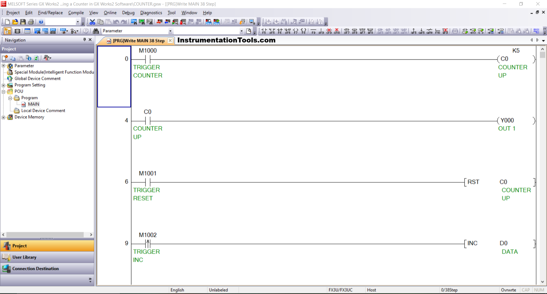
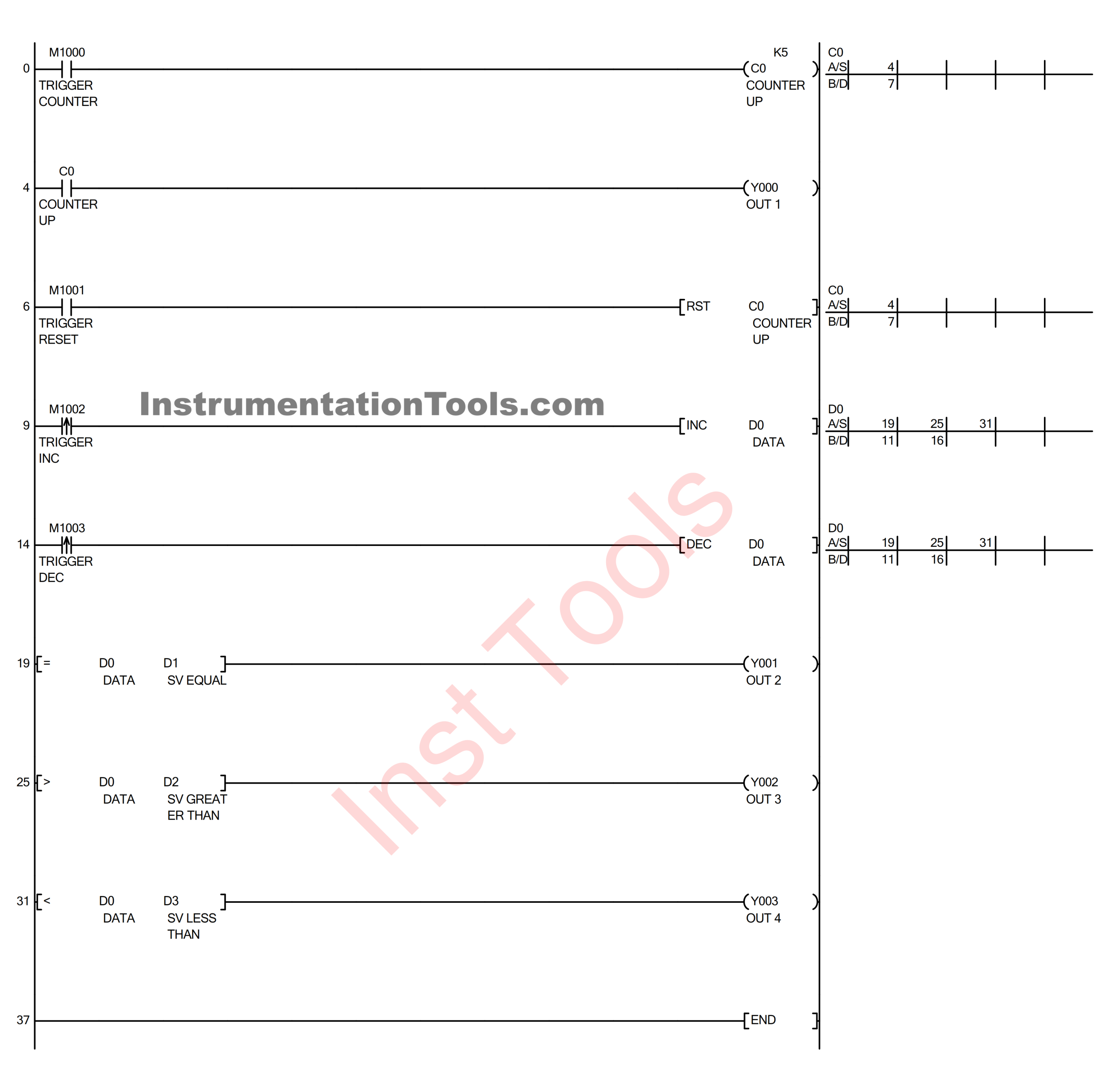
RUNG 0
In this rung, when the TRIGGER COUNTER button (M1000) is pressed, the value of the COUNTER_UP (C0) instruction will increment by “+1”.
When the value of COUNTER_UP (C0) reaches “5”, the counter instruction will turn ON.
RUNG 4
In this rung, Output OUT_1 (Y000) will turn ON if the normally open contact of COUNTER_UP (C0) is in a HIGH state.
RUNG 6
In this rung, if the TRIGGER_RESET button (M1001) is pressed, the value of COUNTER_UP (C0) will be reset to zero (0).
RUNG 9
In this rung, when the TRIG_INC button (M1002) is pressed, the value in the word memory DATA (D0) will increment by “+1”.
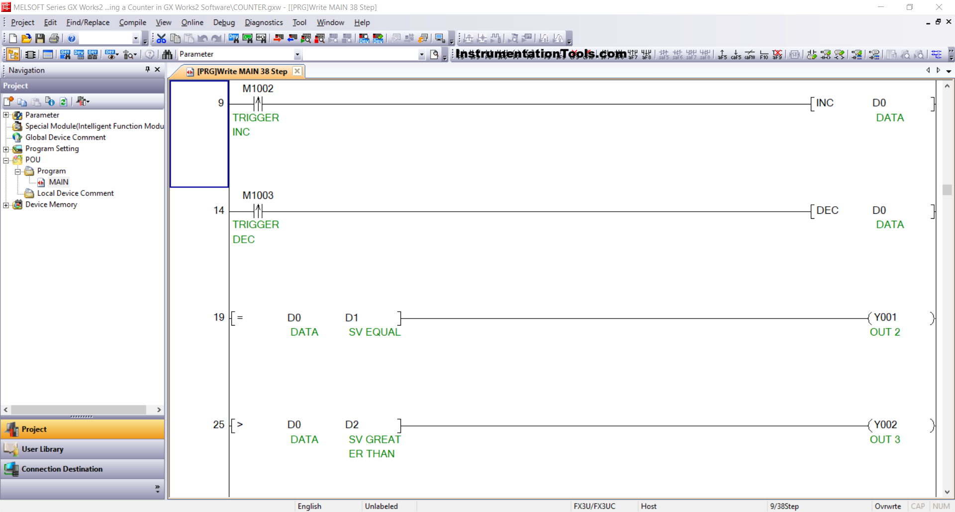
RUNG 14
In this rung, when the TRIG_INC button (M1002) is pressed, the value in the word memory DATA (D0) will decrease by 1.
RUNG 19
When the value in word memory DATA (D0) is equal to SV_EQUAL (D1), Output OUT_2 (Y001) will turn ON.
RUNG 25
When the value in word memory DATA (D0) is greater than SV_GREATER_THAN (D2), Output OUT_3 (Y002) will turn ON.
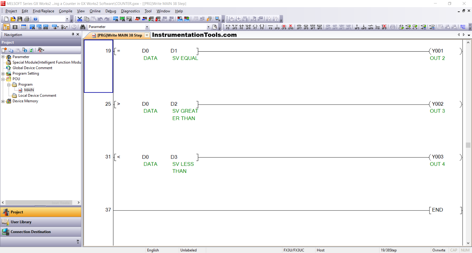
RUNG 31
When the value in word memory DATA (D0) is less than SV_LESS_THAN (D3), Output OUT_4 (Y003) will turn ON.
Read Next:
- PLC Mail Box Automation Programming
- Car Parking Logic in XG5000 LS Electric PLC
- PLC Hoist Crane Programming Example
- Modbus Communication Delta PLC with VFD
- Delta HMI and VFD Control with Modbus


