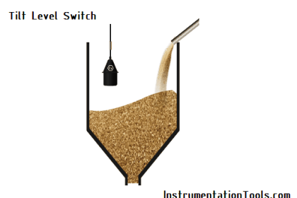
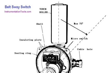
A limit switch detects the physical motion of an object by direct contact with that object. An example of a limit switch is the switch detecting the open position of an automobile door, automatically energizing the cabin light when the door opens.
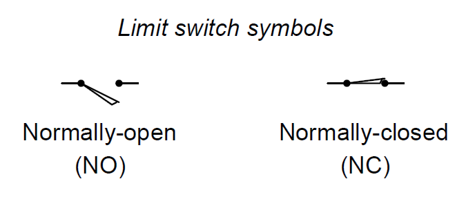
Recall from this article, that the “normal” status of a switch is the resting condition of no stimulation. A limit switch will be in its “normal” status when it is not in contact with anything (i.e. nothing touching the switch actuator mechanism).
Limit switches find many uses in industry, particular in robotic control and CNC (Computer Numerical Control) machine tool systems. In many motion-control systems, the moving elements have “home” positions where the computer assigns a position value of zero. For example, the axis controls on a CNC machine tool such as a lathe or mill all return to their “home” positions upon start-up, so the computer can know with confidence the starting locations of each piece. These home positions are detected by means of limit switches. The computer commands each servo motor to travel fully in one direction until a limit switch on each axis trips. The position counter for each axis resets to zero as soon as the respective limit switch detects that the home position has been reached.
A typical limit switch design uses a roller-tipped lever to make contact with the moving part. Screw terminals on the switch body provide connection points with the NC and NO contacts inside the switch. Most limit switches of this design share a “common” terminal between the NC and NO contacts like this:
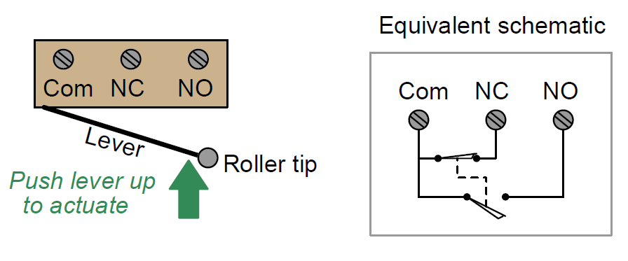
This switch contact arrangement is sometimes referred to as a form-C contact set, since it incorporates both a form-A contact (normally-open) as well as a form-B contact (normally-closed).
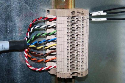
A close-up view of several limit switches (used on a drum sequencer) shows the arrangement of connection terminals for form-C contacts. Each limit switch has its own “NO” (normally-open), “NC” (normally-closed), and “C” (common) screw terminal for wires to attach:

A limit switch assembly attached to the stem of a rotary valve – used to detect the fully-closed and fully-open positions of the valve – is shown in the following photograph:


excellent