Inst ToolsInst ToolsInst Tools
  • Courses
  • Automation
    • PLC
    • Control System
    • Safety System
    • Communication
    • Fire & Gas System
  • Instrumentation
    • Design
    • Pressure
    • Temperature
    • Flow
    • Level
    • Vibration
    • Analyzer
    • Control Valve
    • Switch
    • Calibration
    • Erection & Commissioning
  • Interview
    • Instrumentation
    • Electrical
    • Electronics
    • Practical
  • Q&A
    • Instrumentation
    • Control System
    • Electrical
    • Electronics
    • Analog Electronics
    • Digital Electronics
    • Power Electronics
    • Microprocessor
  • Request
Search
  • Books
  • Software
  • Projects
  • Process
  • Tools
  • Basics
  • Formula
  • Power Plant
  • Root Cause Analysis
  • Electrical Basics
  • Animation
  • Standards
  • 4-20 mA Course
  • Siemens PLC Course
Reading: Two Element Drum Level Control System
Share
Font ResizerAa
Inst ToolsInst Tools
Font ResizerAa
  • Courses
  • Design
  • PLC
  • Interview
  • Control System
Search
  • Courses
  • Automation
    • PLC
    • Control System
    • Safety System
    • Communication
    • Fire & Gas System
  • Instrumentation
    • Design
    • Pressure
    • Temperature
    • Flow
    • Level
    • Vibration
    • Analyzer
    • Control Valve
    • Switch
    • Calibration
    • Erection & Commissioning
  • Interview
    • Instrumentation
    • Electrical
    • Electronics
    • Practical
  • Q&A
    • Instrumentation
    • Control System
    • Electrical
    • Electronics
    • Analog Electronics
    • Digital Electronics
    • Power Electronics
    • Microprocessor
  • Request
Follow US
All rights reserved. Reproduction in whole or in part without written permission is prohibited.
Inst Tools > Blog > Control Systems > Two Element Drum Level Control System

Two Element Drum Level Control System

Last updated: September 4, 2018 2:24 pm
Editorial Staff
Control Systems
No Comments
Share
4 Min Read
SHARE

A two-element drum level control system is capable of providing close adherence of drum level to its set-point under steady-state conditions as well as being capable of providing the required tight control during a transient. Its performance during transient conditions permits its use on many industrial boiler applications. Such applications are characterized by adequately-sized drums used with load changes of moderate rate and degree. These characteristics are usually found in plants with continuous-type processes, and those with mixed heating and processing demands. Caution should be exercised in its use on systems without reasonably constant feedwater pressure.

The term ‘two-element’ is derived from two variables: steam flow and drum level influence on the feedwater valve position. It is often classified as a combination ‘feed-forward-feedback’ system because the steam flow demand is fed forward as the primary index of the feedwater valve position. The drum level signal becomes the feedback which is used to constantly trim the accuracy of the feed-forward system and provide final control of the water/steam interface in the drum.

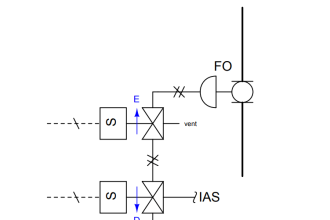
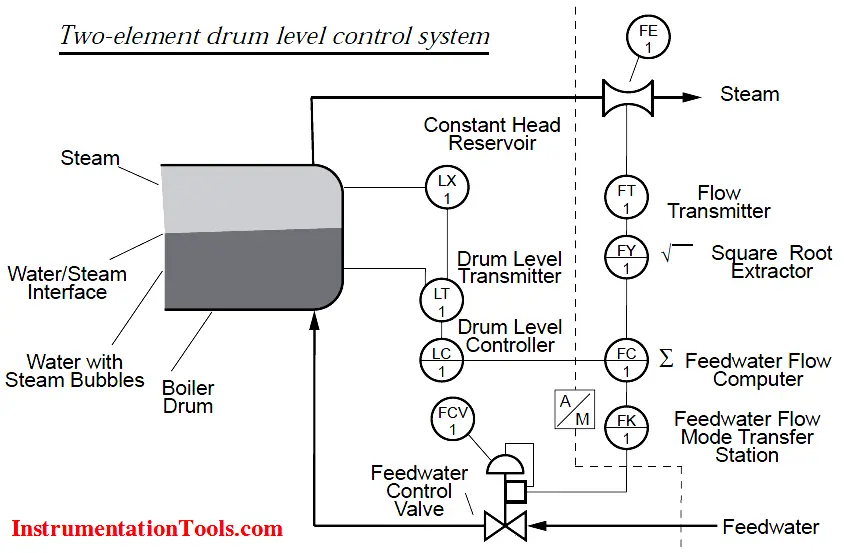
The below Figure for the control scheme of a two-element drum level control. Note the left side of the doted line is identical to that used in single-element control. Additional equipment required for two-element drum level control consists of a steam flow measuring device, a differential pressure transmitter, a square root extractor, a feedwater flow computer and a feedwater flow mode transfer station. At first this may appear like a large investment in order to gain stable drum level control, but as you will see this is not necessarily true.

Two-element drum level control system

How it works:

Steam flow is measured by the steam flow transmitter (FT-1), its signal is fed to the feedwater flow computer or flow controller (FC-1) after processing through the square root extractor (FY-1) (Note: Square root extractor function is an inbuilt option utilized either in transmitter or controller). As in the single-element level control, the drum level is measured by the level transmitter (LT-1) and its signal is transmitted to the drum level controller (LC-1). In the drum level controller, the process signal is compared to the drum level set-point, where a required corrective output signal to maintain the drum level is produced. This corrective signal is sent to the feedwater flow computer. The feedwater flow computer combines the signal from the two variables, and produces an output signal to the feedwater control valve (FCV-1). Auto/Manual transfer of the feedwater control valve is accomplished via FK-1.

Nearly all of the load change work is done by the feed-forward system, for example, a pound of feedwater change is made for every pound of steam flow change. The drum level control system is used for compensation only.

It is expected that the drum level will be maintained very closely to the set-point value. This is true in spite of the low-to-moderate volume/throughput ratio and a wide operating range. As a result, integral response (reset) is a necessary function in the drum level controller.

Source : ABB

Don't Miss Our Updates
Be the first to get exclusive content straight to your email.
We promise not to spam you. You can unsubscribe at any time.
Invalid email address
You've successfully subscribed !

Continue Reading

Difference Between Optical Fibre and Coaxial Cable
SCADA Systems
Overview of Woodward Governor 505
How to Import PlantPAx Library?
PID Controller Functions
What is Open Telemetry? – Principles and Benefits
Share This Article
Facebook Whatsapp Whatsapp LinkedIn Copy Link
Share
Leave a Comment

Leave a Reply Cancel reply

Your email address will not be published. Required fields are marked *

Stay Connected

128.3kFollowersLike
69.1kFollowersFollow
210kSubscribersSubscribe
38kFollowersFollow

Categories

Explore More

Basic Process Control System
How to tune a PID Controller ?
PID Controllers Graphical Analysis
Proportional Controller Principle
Cascade Control
Why 24 Volts DC Power Supply is used? – Industrial Automation Systems
Switches, Repeaters, Bridges, Routers, Firewalls
Two out of Three Logic Analogy

Keep Learning

DCS Vs PLC

Difference between DCS & PLC Systems

Adaptive Controller Overview

What is Adaptive Control?

Design Logic Diagrams with Standard Formats for Process Control

Design Logic Diagrams with Standard Formats for Process Control

Functional Design Specifications (FDS) for DCS and SIS Projects

Functional Design Specifications for DCS and SIS Projects – FDS Document

DCS Vs PLC

DCS versus PLC Architecture

Difference Between Single Pair Ethernet and Traditional Ethernet

Difference Between Single Pair Ethernet and Traditional Ethernet

DCS ESD Logic Overview Graphic Display

Automation System Process Functionalities

Open Systems Interconnection

What is Open Systems Interconnection?

Learn More

Closed Tank - Dry Reference Leg

Basics of Level Measurement

Power Electronics Objective Questions

Thyristor Gating Circuits Objective Questions

DP-Level-Measurement-Calculation-Below-Tapping-Point-Open-Tank

Differential Pressure (DP) Level transmitter Installed Below Tapping Point

PID-Controller-Selection

PID Controller Selection

Calculate LRV and URV for 4-20 mA Loop-powered DP Transmitter

Calculate LRV and URV for 4-20 mA Loop-powered DP Transmitter

Robot Anatomy

Robot – Anatomy, Configuration, Reference Frame, Characteristics

Identification of Equipment Standards

Identification of Equipment

Piping and Instrumentation Diagram

What is Piping and Instrumentation Diagram (P&ID) ?

Menu

  • About
  • Privacy Policy
  • Copyright

Quick Links

  • Learn PLC
  • Helping Hand
  • Part Time Job

YouTube Subscribe

Follow US
All rights reserved. Reproduction in whole or in part without written permission is prohibited.
Welcome Back!

Sign in to your account

Username or Email Address
Password

Lost your password?