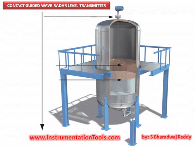
In previous articles we discussed different types of Blocks in SIEMENS TIA Portal, we talked about function blocks FBs, functions FCs, and data blocks DBs.
In this article we will take about another type of block in SIEMENS PLCs, these are the organization blocks, and in this article, we will discuss the most important organization block of them all, which is the Main Organization Block or OB1.
Contents:
- What are organization blocks?
- Different types of OBs.
- What is OB1?
- Cycle time monitoring.
- Simple program example.
- Conclusion.
What is an Organization Block (OB)?
Organization blocks, you can think of them as functions FCs or function blocks FBs. But the difference is, you don’t call them, the operating system of the PLC calls these organization blocks, whether the operating system calls the OB cyclically as OB1 or whether it gets called when a certain event occurs, either way, the operating system takes care of it. You only need to create the block and add whatever logic you want inside the block. Sometimes you don’t even need to add any code inside the OB, just creating the OB itself can provide many benefits, which we will see when discussing some of those OBs.
Organization blocks are the interface between the PLC operating system and the user program. Any PLC will have two different programs, the runtime program which is the operating system of the PLC, and the user program which is the logic or code that the PLC programmer will write to control a certain process. This two different software need to talk with each other, and the organization blocks OBs are how that is done.
Organization blocks OBs are used to perform a lot of tasks, some of which are listed below:
- Startup characteristics of the automation system
- Cyclic program processing
- Interrupt-driven program execution
- Error handling.
Different Types of Organization Blocks
As organization blocks are basically the tools of the operating system to perform a lot of tasks.
Different tasks require different OB, and that is why you have many different OBs inside a PLC, how many different OBs will depend on the type of PLC you are using, but here are some of the most common OBs you can find in almost all of SIEMENS PLC:
- Main Cyclic OB1.
- Time interrupts OBs.
- Time of day OBs.
- Software errors OBs.
- Hardware errors OBs
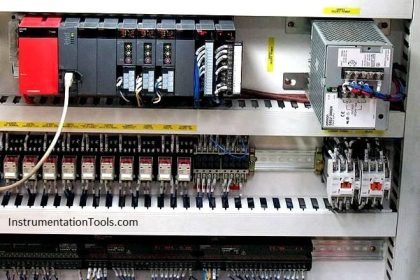
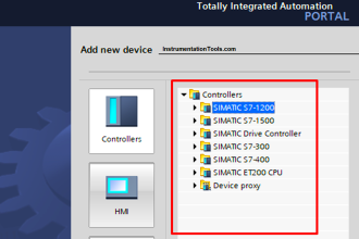
Many more Organization blocks are available for use with your logic. See picture 1.
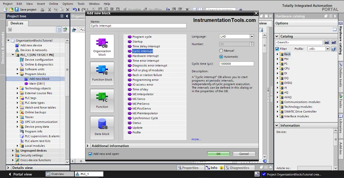
In this article, we will discuss the most important organization block of them all, which is the Main Cyclic Interrupt OB1.
Main Cyclic Interrupt OB1
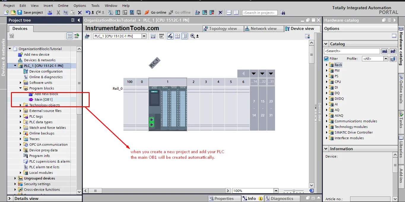
The main cyclic OB1 is the organization block which is responsible for cyclically executing your logic by the PLC. Whenever you create a new project and add a PLC, the Main OB1 will be automatically created by the software. These are the minimum needed blocks for a PLC code. See picture 2.
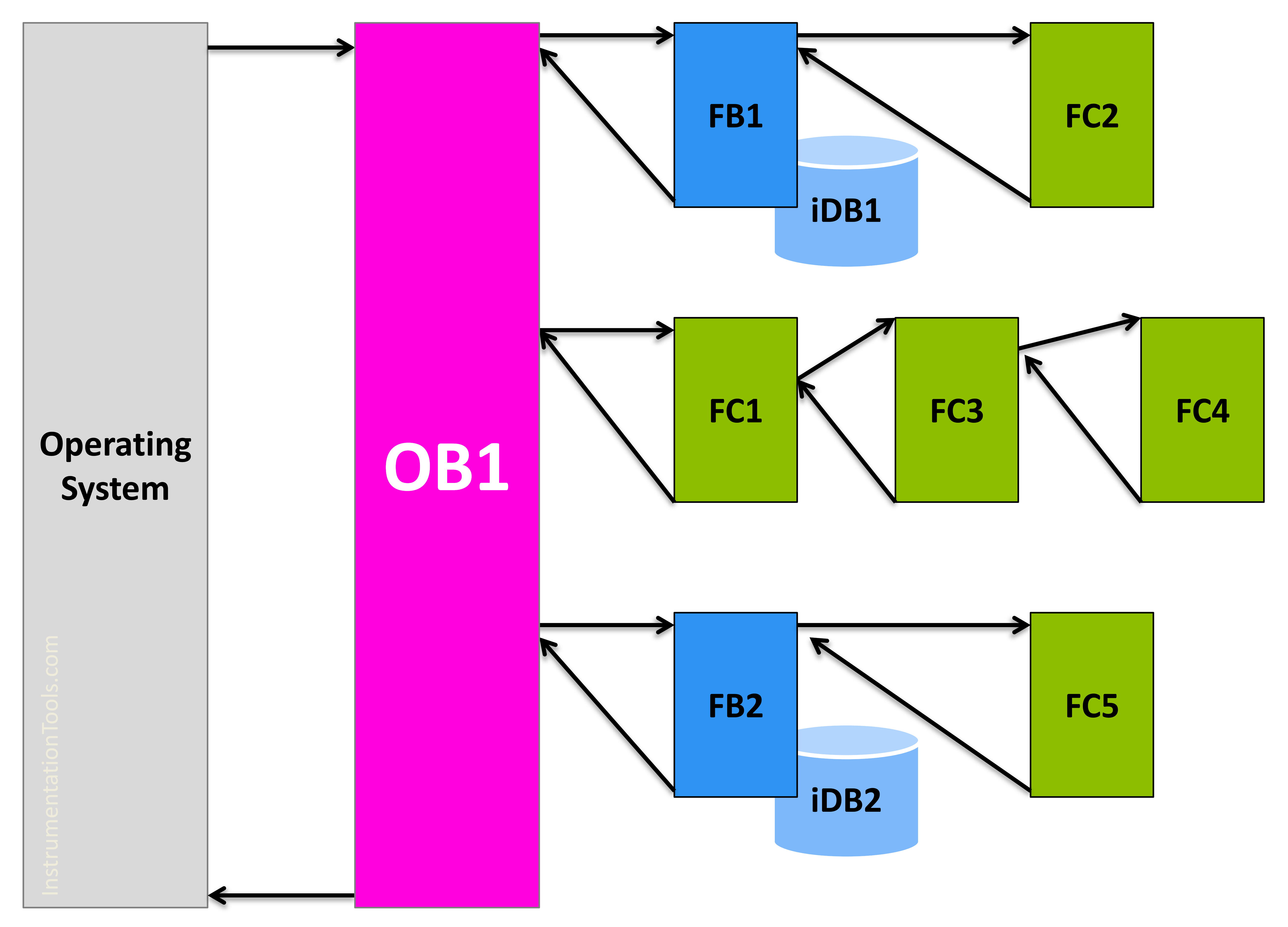
Inside this Main OB1, you can either write your whole PLC program if it is a small project. If your project is quite large, then you probably have some functions FCs of function blocks FBs that you need to execute. In that case, you will use the Main OB1 to call them.
Off course, you don’t have to call every FC or FB by the OB1, but if your OB1 is not the first block of your nesting calls, then it will not be executed. See picture 3.
The essential basis of your PLC code is the cyclic behavior, meaning you need your code to be executed continuously. When the processing of your logic has been completed, the operating system starts processing it again. That is done through the use of the main OB1, you put and call all of your logic and code inside this OB1 and the operating system will make sure to continuously execute it.
You should know that, even if you can’t create an OB1 block as it is automatically created when adding a new PLC, you can create more than one cyclic interrupt block.
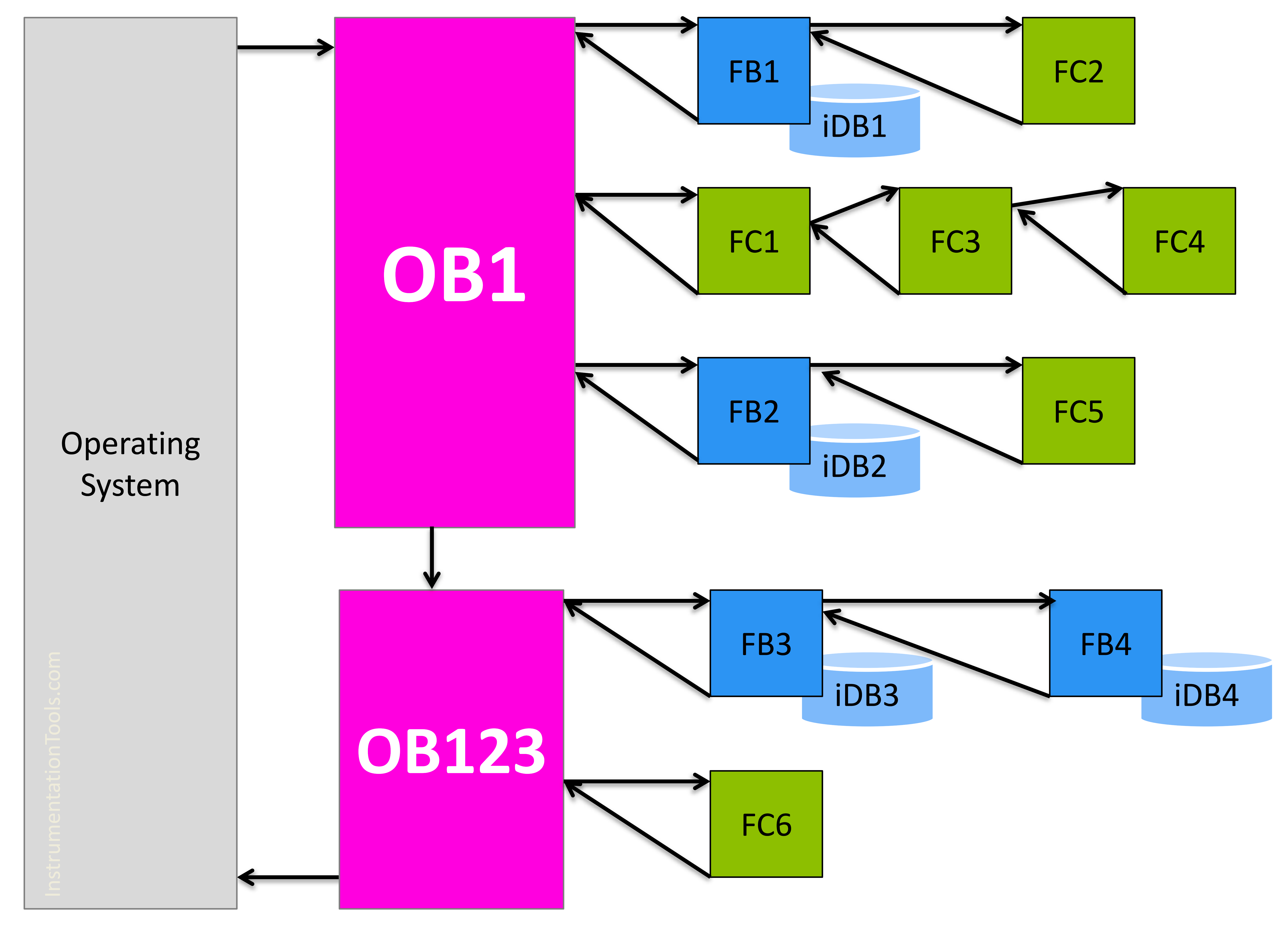
OB1 is a cyclic interrupt, that the operating system will automatically and continuously call and executed whatever logic is inside. However, for large PLC projects where you have so many functions and function blocks in your PLC logic, you can use more than one cyclic interrupt OB to better structure your code to make it easy to read and follow.
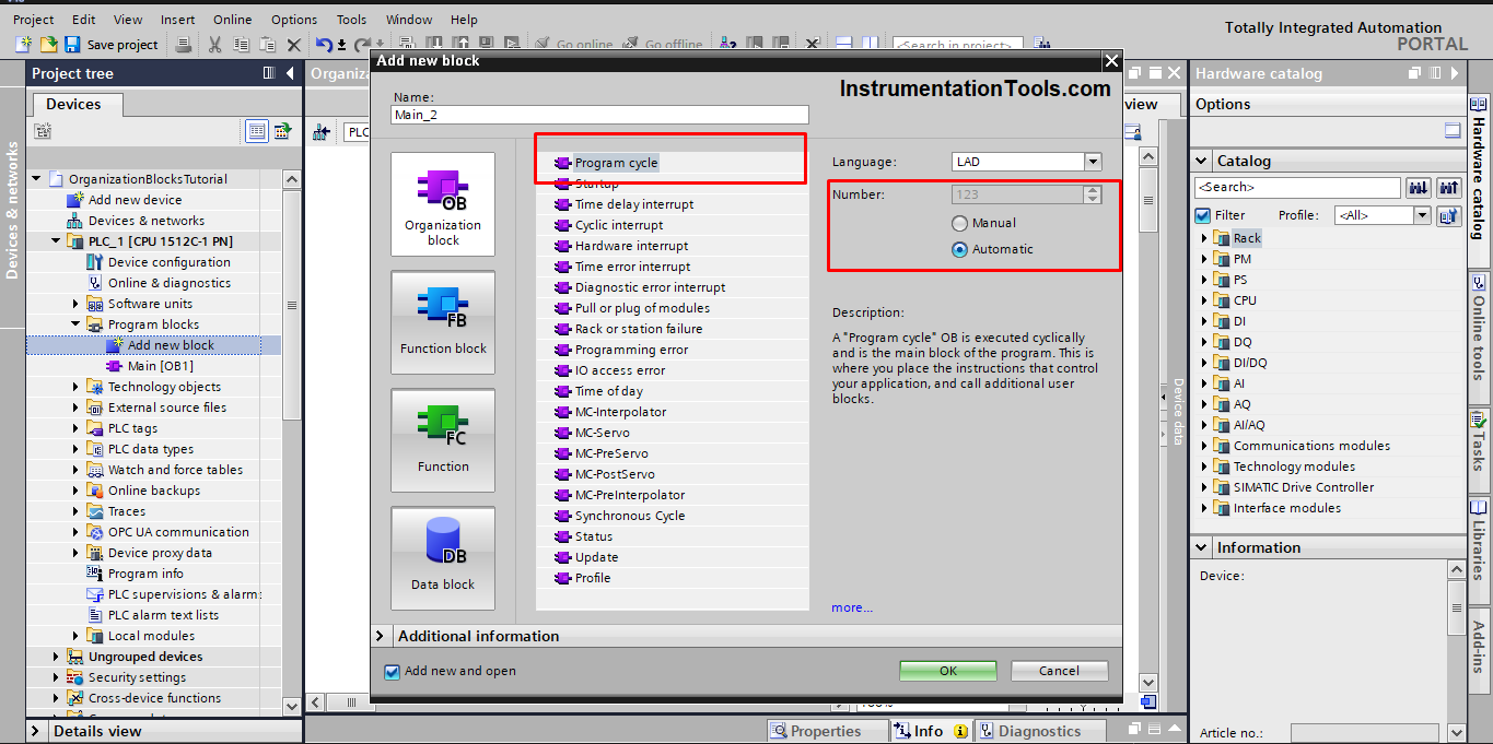
In that case, you would create another cyclic interrupt, see picture 4.
When you have created several program cycle OBs, these are called one after the other in the order of their OB numbers.
The program cycle OB with the lowest OB number is called first. See picture 5.
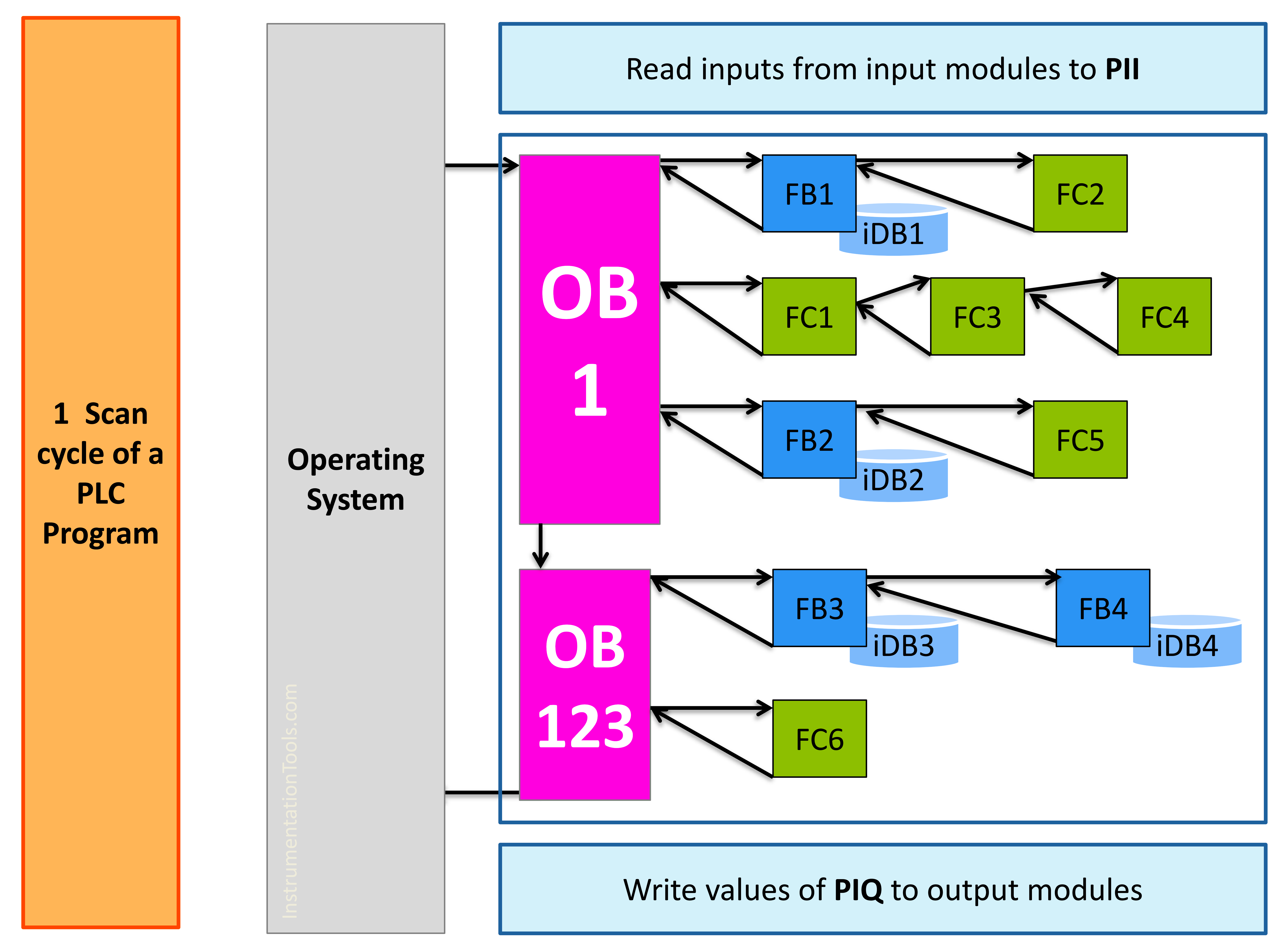
After the cyclic program is complete, the operating system updates the process images as follows:
- It writes the values from the process image output to the output modules.
- It reads the inputs at the input modules and transfers these to the process image input.
The previous two steps plus the execution of the PLC program are called a scan cycle. See picture 6.
Cycle Time Monitoring
Cycle time refers to the runtime of the cyclic program, including the runtime of all nested program parts like FCs, FBs, and higher-priority OBs. If you have created several program cycle OBs, each program cycle OB contributes to the cycle time.
The operating system monitors whether the cycle time remains smaller than the configured maximum cycle time. If it exceeds the maximum cycle time, PLC will either go to STOP mode or call OB80 depending on your programming.
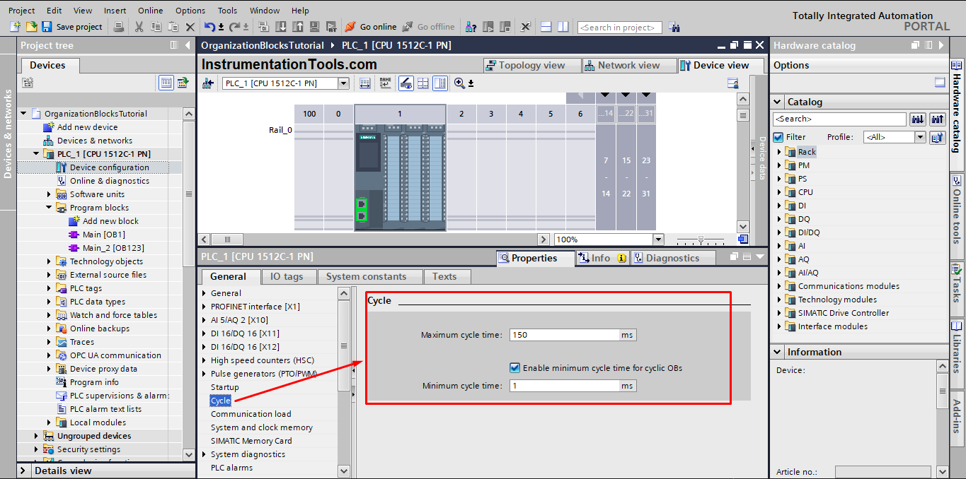
Apart from monitoring the maximum cycle time, it is also possible to guarantee a minimum cycle time. To do this, the operating system delays the start of a new cycle until the minimum cycle time has been reached.
You can configure the minimum and maximum cycle time in the configuration properties of your PLC. See picture 7.
Simple Program Example in PLC
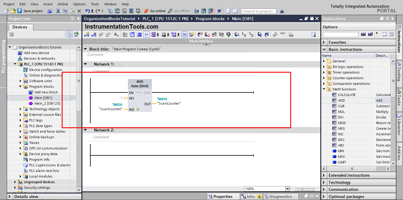
To better understand the PLC program cycle and OB1 execution, let’s create a simple program. This program will use an add instruction that will accumulate a value of 1 into a memory area each 1 scan cycle. See the following simulation.
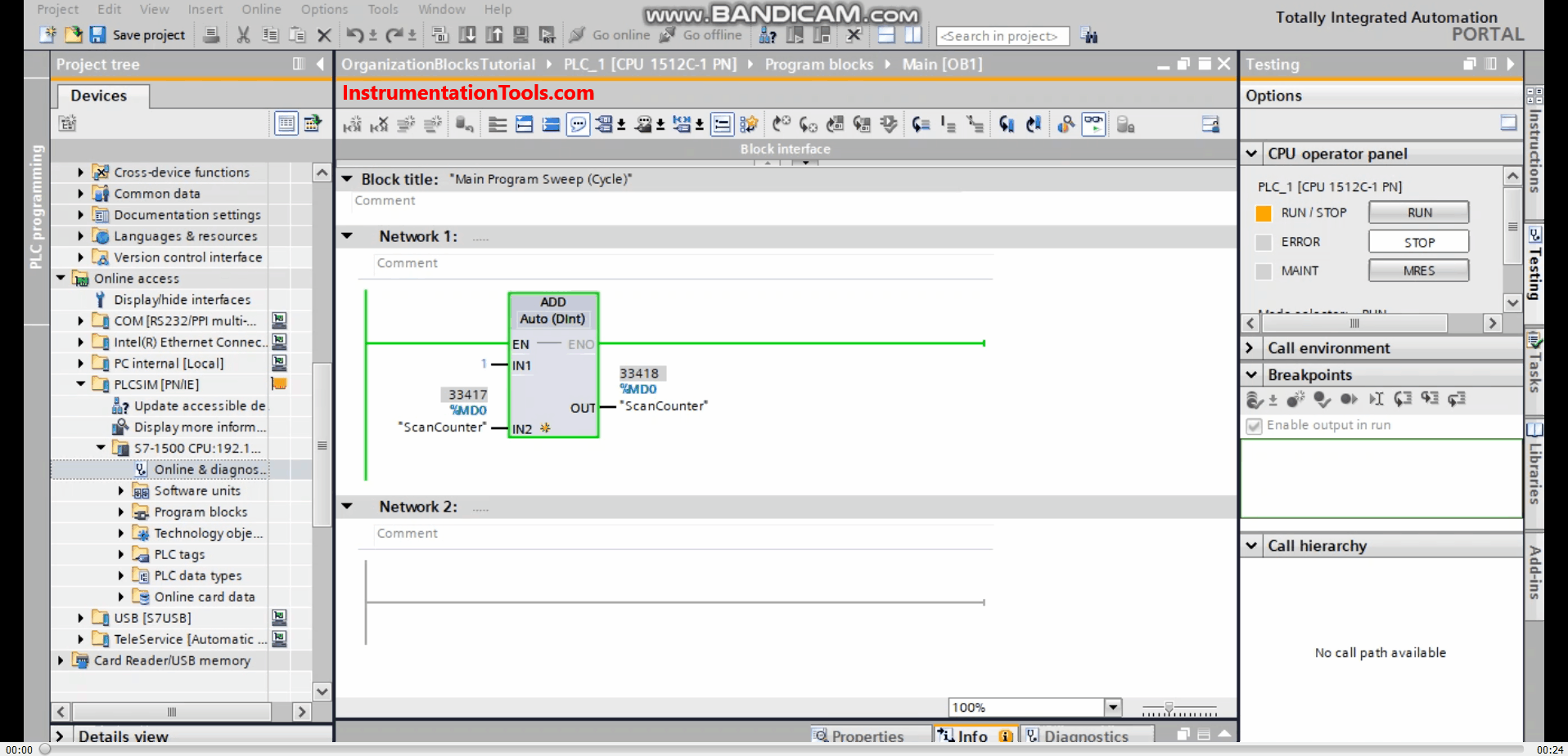
As you see from the animation, the add instruction is being executed very fast; this is how fast the scan cycle is. It will depend on how powerful your PLC is. But mainly the scan cycle is in the range of milliseconds.
Downloads:
Conclusion
- Organization blocks are the interface between the PLC operating system and your control program.
- Main Cyclic OB1 is cyclically executed by the operating system.
- You will execute your logic by including it inside one or more Cyclic OBs.
- The scan cycle time is the time used to execute your logic 1 time.
If you liked this article, then please subscribe to our YouTube Channel for Instrumentation, Electrical, PLC, and SCADA video tutorials.
You can also follow us on Facebook and Twitter to receive daily updates.
Read Next:
- System and Local Time in PLC
- PLC Programming Tips & Tricks
- Timers in Siemens Tia Portal
- SCADA System Architecture
- Static and Temp Variables in PLC


That is very interesting article just keep on