Inst ToolsInst ToolsInst Tools
  • Courses
  • Automation
    • PLC
    • Control System
    • Safety System
    • Communication
    • Fire & Gas System
  • Instrumentation
    • Design
    • Pressure
    • Temperature
    • Flow
    • Level
    • Vibration
    • Analyzer
    • Control Valve
    • Switch
    • Calibration
    • Erection & Commissioning
  • Interview
    • Instrumentation
    • Electrical
    • Electronics
    • Practical
  • Q&A
    • Instrumentation
    • Control System
    • Electrical
    • Electronics
    • Analog Electronics
    • Digital Electronics
    • Power Electronics
    • Microprocessor
Search
  • Books
  • Software
  • Projects
  • Process
  • Tools
  • Basics
  • Formula
  • Power Plant
  • Root Cause Analysis
  • Electrical Basics
  • Animation
  • Standards
  • 4-20 mA Course
  • Siemens PLC Course
Reading: Loop-powered 4-20 mA Transmitter Circuit Voltage drop
Share
Notification Show More
Font ResizerAa
Inst ToolsInst Tools
Font ResizerAa
  • Courses
  • Design
  • PLC
  • Interview
  • Control System
Search
  • Courses
  • Automation
    • PLC
    • Control System
    • Safety System
    • Communication
    • Fire & Gas System
  • Instrumentation
    • Design
    • Pressure
    • Temperature
    • Flow
    • Level
    • Vibration
    • Analyzer
    • Control Valve
    • Switch
    • Calibration
    • Erection & Commissioning
  • Interview
    • Instrumentation
    • Electrical
    • Electronics
    • Practical
  • Q&A
    • Instrumentation
    • Control System
    • Electrical
    • Electronics
    • Analog Electronics
    • Digital Electronics
    • Power Electronics
    • Microprocessor
Follow US
All rights reserved. Reproduction in whole or in part without written permission is prohibited.
Inst Tools > Blog > Control Systems > Loop-powered 4-20 mA Transmitter Circuit Voltage drop

Loop-powered 4-20 mA Transmitter Circuit Voltage drop

Last updated: February 10, 2020 3:15 pm
Editorial Staff
Control Systems
2 Comments
Share
2 Min Read
SHARE

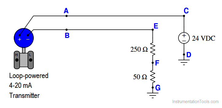
Calculate the voltage drops in this loop-powered 4-20 mA transmitter circuit for the current conditions 4mA, 8mA, 12mA, 20mA.

Loop-powered 4-20 mA Transmitter

Loop-powered 4-20 mA transmitter

Calculate the voltage drop at different points in the above circuit, like VCD, VEF, VFG, VAB at different loop currents (4mA, 8mA, 12mA, and 20mA)

In order for a loop-powered transmitter such as this to function adequately, there must be a minimum DC voltage between its terminals (VAB) at all times.

A typical value for this voltage is 12 volts (be aware that this minimum voltage level varies considerably between different manufacturers and models!). Identify what loop condition(s) may jeopardize this minimum supply voltage value, and how you as a technician would ensure the transmitter always received enough voltage to function.

Solution:

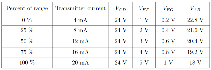
The Rosemount 3144 temperature transmitter, for example, requires a minimum of 12 volts at its terminals to function in the analog mode, and 18.1 volts in order to properly function while communicating using the HART digital-over-analog protocol.

Note how the operation of such a 3144 transmitter in a loop with a 24 volt power supply and 300 ohms worth of resistance would be jeopardized near the upper end of the signal range.

4-20 mA Transmitter Voltage Drop

Questions for You:

  1. If a technician happened to be measuring transmitter terminal voltage while the pressure applied to the “H” port of the transmitter suddenly increased, would the measured voltage increase or decrease?
  2. This circuit shows two resistors, rather than just one. Identify a practical reason why a 4-20 mA loop circuit might have multiple resistances in it.
  3. Demonstrate how to estimate numerical answers for this problem without using a calculator.

Share Your Answers for the remaining questions.

Credits: Tony R. Kuphaldt

Read Next:

  • What is Instrument  Loop Check?
  • HART Communicator Questions
  • Current-to-Pressure Transducer
  • Inductive Proximity Switch
  • Loop Power Supply Questions
Don't Miss Our Updates
Be the first to get exclusive content straight to your email.
We promise not to spam you. You can unsubscribe at any time.
Invalid email address
You've successfully subscribed !

Continue Reading

Feedforward Vs Feedback Control
Types of SCADA System Architecture
How to Configure a Smart Transmitter Using a HART Communicator?
What is a Floating License? – Automation Software Systems
What is Process Override Switch (POS)?
4-20 mA Transmitter Wiring Types : 2-Wire, 3-Wire, 4-Wire
Share This Article
Facebook Whatsapp Whatsapp LinkedIn Copy Link
Share
2 Comments
  • hayder azeez says:
    February 4, 2021 at 1:57 pm

    1- increase .
    2- I am not sure and i hope to known the reason for that , I think we used multiple resistances to compare the value of volts for each resistance the insurance that is no deviation or drop of voltage .
    3-we can used multimeter to read values for each segment between nodes and used Kirchhoff voltage law then compare the results with state of level transmitter.

    Reply
  • Azetou says:
    April 13, 2023 at 4:16 pm

    What about the internal resistance of the transmitter? why it is not taken into account ?

    Reply

Leave a Reply Cancel reply

Your email address will not be published. Required fields are marked *

Stay Connected

128.3kFollowersLike
69.1kFollowersFollow
210kSubscribersSubscribe
38kFollowersFollow

Categories

Explore More

Proportional-only Offset
Proportional Integral Derivative Controllers – PID MCQ
How to Export Data from DeltaV System to Excel
Setpoints and Alarms in Control System
On/off Control Theory
Loop Calibrator to Simulate a 4-20 mA Signal
Waste Water Control System
What is Energy Monitoring System ?

Keep Learning

Compare Serial and Parallel Communication

Difference Between Serial and Parallel Communication

Direct digital control principle

Direct Digital Control (DDC) Systems

Modern Industrial Joystick Controls

Installing and Using Modern Industrial Joystick Controls

Problem in Water Level Control System

Problem in Water Level Control System

Yokogawa DCS Tutorials - Configuration of Analog Input (Transmitter)

Yokogawa DCS Tutorials – Configuration of Analog Input (Transmitter)

FF JB Termination

Foundation Fieldbus Installation and Best Practices

Switches, Repeaters, Bridges, Routers, Firewalls

Purpose of Gateways, Bridges & Routers in Networking

Instrument Control Package (ICP)

Package Control and Safety Systems Implementation Methods

Learn More

Phase angle

AC Generation Analysis : Effective Values, Phase Angle and Frequency

DCS Quiz

DCS Quiz

Car Parking System PLC Program Example

Schneider Electric: Car Parking System with Calculations in PLC

PLC based 4 Way Traffic Light Control System

PLC based 4 Way Traffic Light Control System

Free Siemens PLC Training Course

Free Siemens PLC Training Course

Resistance firing of an SCR in a half-wave circuit

Thyristor Triggering Circuits – Types, Explanation, Waveforms (SCR)

Trolley and hoist PLC control

PLC Crane Movement Control with Limit Switches

30 Concerns for Control System Philosophy (Industrial Automation)

30 Concerns for Process Control Systems Philosophy

Menu

  • About
  • Privacy Policy
  • Copyright

Quick Links

  • Learn PLC
  • Helping Hand
  • Part Time Job

YouTube Subscribe

Follow US
All rights reserved. Reproduction in whole or in part without written permission is prohibited.
Welcome Back!

Sign in to your account

Username or Email Address
Password

Lost your password?