Inst ToolsInst ToolsInst Tools
  • Courses
  • Automation
    • PLC
    • Control System
    • Safety System
    • Communication
    • Fire & Gas System
  • Instrumentation
    • Design
    • Pressure
    • Temperature
    • Flow
    • Level
    • Vibration
    • Analyzer
    • Control Valve
    • Switch
    • Calibration
    • Erection & Commissioning
  • Interview
    • Instrumentation
    • Electrical
    • Electronics
    • Practical
  • Q&A
    • Instrumentation
    • Control System
    • Electrical
    • Electronics
    • Analog Electronics
    • Digital Electronics
    • Power Electronics
    • Microprocessor
  • Request
Search
  • Books
  • Software
  • Projects
  • Process
  • Tools
  • Basics
  • Formula
  • Power Plant
  • Root Cause Analysis
  • Electrical Basics
  • Animation
  • Standards
  • 4-20 mA Course
  • Siemens PLC Course
Reading: Ladder Logic Example of Two Motors Interlinked with another Motor
Share
Font ResizerAa
Inst ToolsInst Tools
Font ResizerAa
  • Courses
  • Design
  • PLC
  • Interview
  • Control System
Search
  • Courses
  • Automation
    • PLC
    • Control System
    • Safety System
    • Communication
    • Fire & Gas System
  • Instrumentation
    • Design
    • Pressure
    • Temperature
    • Flow
    • Level
    • Vibration
    • Analyzer
    • Control Valve
    • Switch
    • Calibration
    • Erection & Commissioning
  • Interview
    • Instrumentation
    • Electrical
    • Electronics
    • Practical
  • Q&A
    • Instrumentation
    • Control System
    • Electrical
    • Electronics
    • Analog Electronics
    • Digital Electronics
    • Power Electronics
    • Microprocessor
  • Request
Follow US
All rights reserved. Reproduction in whole or in part without written permission is prohibited.
Inst Tools > Blog > PLC Tutorials > Ladder Logic Example of Two Motors Interlinked with another Motor

Ladder Logic Example of Two Motors Interlinked with another Motor

In this article, we will learn a ladder logic example of two motors interlinked with another motor in PLC programming.

Last updated: September 28, 2022 4:09 pm
Viral Nagda
PLC Tutorials
No Comments
Share
3 Min Read
SHARE

In this article, we will learn a ladder logic example of two motors interlinked with another motor.

Contents
Ladder Logic Example of Two MotorsFirst RungSecond RungThird Rung

In this post, we will study a case of ladder logic. There are two motors – motor A & motor B. And third motor – C is interlinked with both these motors.

There will be a selection for running the two motors of A & B either simultaneously or individually.

If either the motors (A/B) or a single motor is running depending upon the selection, then the third motor will run.

If any single motor is off, then the third motor too will remain off.

Ladder Logic Example of Two Motors

Let us have a look at the ladder logic for the same accordingly.
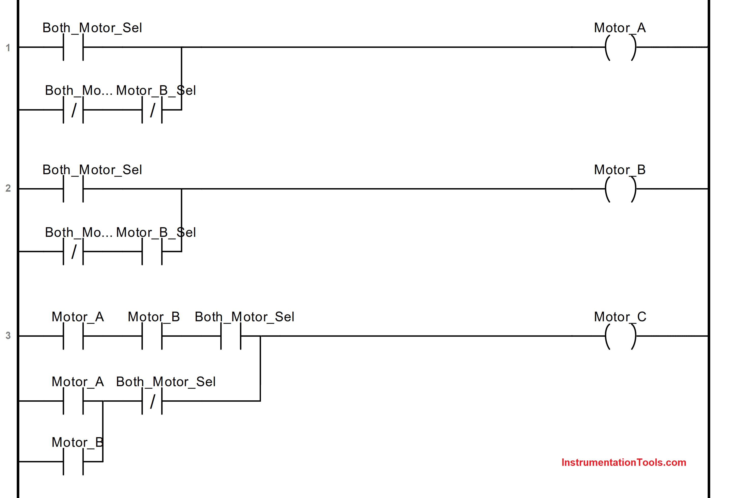
Ladder Logic Example of Two Motors

Refer to the below image for the logic written. Let us understand each rung one by one.

First Rung

The first rung is used to turn on or off the first motor – A. If both the motors are selected to be running, then this motor will run.

If only a single motor is selected to be running, then depending upon the motor selection, this motor will operate.

In this case, the selection input must be off for turning on the output.

Second Rung

The second rung is used to turn on or off the second motor – B. If both the motors are selected to be running, then this motor will run.

If only a single motor is selected to be running, then depending upon the motor selection, this motor will operate.

In this case, the selection input must be on for turning on the output.

Third Rung

The third rung is used to turn on or off the third motor – C. If both the motors are selected to be running, then this motor will run only when both the previous motors are running.

If only a single motor is selected to be running, then this motor will run if either of the output is running.

In this way, we had a case study of the following example in ladder logic.

If you liked this article, then please subscribe to our YouTube Channel for Electrical, Electronics, Instrumentation, PLC, and SCADA video tutorials.

You can also follow us on Facebook and Twitter to receive daily updates.

Read Next:

  • Ladder Logic Example
  • WinCC Runtime Advanced
  • Why 24 Volts DC Power Supply?
  • Communication in S7-1200 PLC
  • Factory Acceptance Test of PLC
Don't Miss Our Updates
Be the first to get exclusive content straight to your email.
We promise not to spam you. You can unsubscribe at any time.
Invalid email address
You've successfully subscribed !

Continue Reading

Working Principle of Single Phase Preventer Relay
PLC Programming for Weight-Based Packaging
Example of Flip-Flop PLC Program for Lamps Application
PID Controller Output Types – PID_PWM and PID_Output
PLC Temperature Control using Pulse Width Modulation (PWM)
ControlLogix Architecture – Rockwell Automation
Share This Article
Facebook Whatsapp Whatsapp LinkedIn Copy Link
Share
Leave a Comment

Leave a Reply Cancel reply

Your email address will not be published. Required fields are marked *

Stay Connected

128.3kFollowersLike
69.1kFollowersFollow
210kSubscribersSubscribe
38kFollowersFollow

Categories

Explore More

Forcing and Modifying PLC Logic
Motor Feedback Fail Logic in PLC
Automatic Highway Lights Program using RTC in Omron PLC
PLC Programming Example using Limit Switch
Elevator PLC Ladder Logic
How to Configure IP Address in Rockwell PLC?
How to Read the PLC Datasheet? – Important Notes About PLC
Difference Between SCADA and HMI

Keep Learning

PLC Program for Temperature Control using Thermostat

PLC Program for Temperature Control using Thermostat

Relay Motor Logic Circuit

Motor Control Circuits

FIFO in STL Language in Siemens PLC

How to Code a FIFO Queue in STL Language in Siemens PLC?

Top 5 Advantages of Human-Machine Interface (HMI)

Top 5 Advantages of Human-Machine Interface (HMI)

Types of PLC

Types of PLC

PLC Program for Alarm Indication in Process

PLC Program for Alarm Indication in Process Control

Structured Text PLC Program for Sequential Process Data Storage

Structured Text PLC Code for Sequential Process Data Storage

Difference between Compact PLC and Modular PLC

Difference between Compact PLC and Modular PLC

Learn More

Sources of Static Grounding and Methods to Control

Sources of Static Grounding and Methods to Control

double-pumps unit unloading valves

What is an Unloading Valve? – Types, Principle

5 Most Common Mistakes When Specifying Valves

5 Most Common Mistakes When Specifying Valves

Pressure Gauge Accessories

Pressure Gauge Accessories

30% Feed Control Valve

Purpose of 100% and 30% Feed Control Valves in a Power Plant

Electrical Machines Objective Questions

Electrical Machines MCQ Series 22

What is a Voltage Reference

What is a Voltage Reference? – Electronic Components

What is a Laser Sensor

What is a Laser Sensor? Principle

Menu

  • About
  • Privacy Policy
  • Copyright

Quick Links

  • Learn PLC
  • Helping Hand
  • Part Time Job

YouTube Subscribe

Follow US
All rights reserved. Reproduction in whole or in part without written permission is prohibited.
Welcome Back!

Sign in to your account

Username or Email Address
Password

Lost your password?