Tube Stretch or Pickup
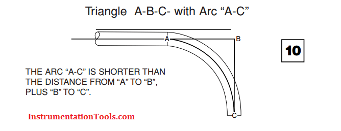
When bent, tubing seems to stretch or pick up length. This is because it takes a curved shortcut across the inside of the angle. A good “rule of thumb” for most standard tubing materials and radius blocks is that the tubing will stretch approximately one tube diameter for each 90° bend.
Always try to bend in the same direction – away from the original starting end. If you reverse the direction of bending (bending towards instead of away from the original starting end) you will “trap” the stretch. Thus, if you unknowingly make a reverse bend of 90°, you will trap the gain, in table 11 (approximately one tube O.D.) and increase your length between bends by that amount.
If bend direction for either 45° or 90° bend must be reversed, subtract the “gain” amount listed in table 11.
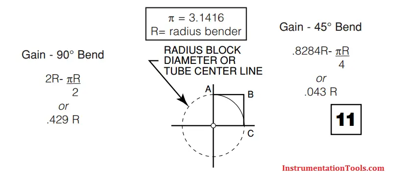
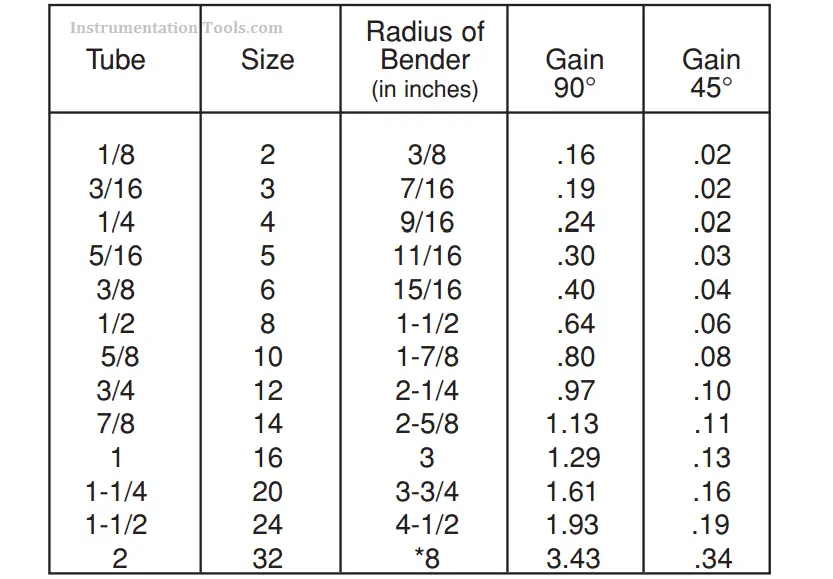
While our rule of thumb is approximately correct, the amount of stretch is related to the diameter of the radius block used. This chart (Figure 11) gives the accurate increase in length that occurs with the most commonly used sizes of radius blocks.
As long as you measure and bend with the tube inserted from the left, and measure centerline, “pickup” will not affect your actual centerto-center measurement.
NOTE: Some radius blocks may differ. Consult individual radius block manufacturers for details on other radius diameters.
Pre-Measuring
You may pre-measure a series of bends. Measure the first bend from the end of the tube, the correct length. Compensate for each bend after the first by subtracting the amount of gain from your chart for each 90° of bend to allow for stretch (Figure 11). Always custom measure for the last bend.
“Rule of Thumb” Method
Compensate each measurement after the first by subtracting the gain listed in above mentioned table 11.
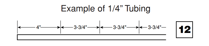
Best Way to Measure
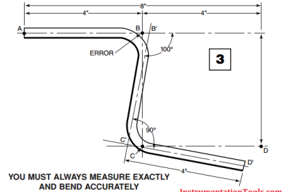
For maximum accuracy, measure and bend exactly for each individual bend in the tubing line. We recommend the practice of Measure and Bend, Measure and Bend, etc.
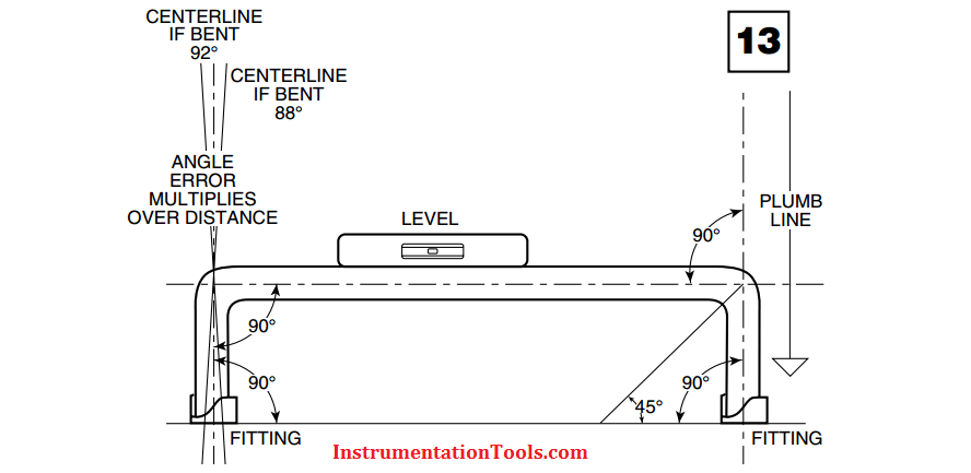
Characteristics of a Well-Made Tubing Circuit
In a well made tubing circuit or line, bends are accurate, measurement exact. The run is plumb, square and level. Tube ends rest firmly in the fittings and entry into the fittings is straight. Straight tube entry is very important to insure that fittings are not under stress and can be assembled without leaks. (Figure 13)
Remember too, that length magnifies bend angles errors. If the leg following the bend is fairly long, an error of 1° may result in the tube line missing the desired point completely.
Properly Made Tube Circuit
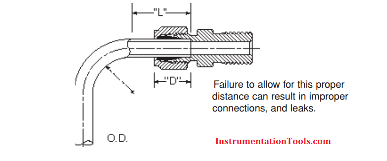
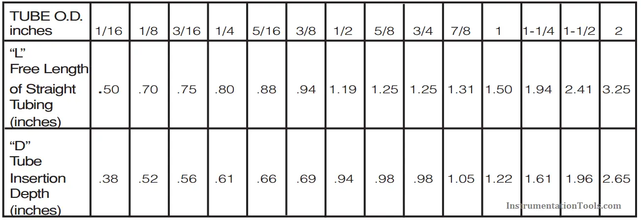
Recommended Free Tubing Lengths
It is important to consider the length of tubing from the end in the fitting body to the beginning of the bend.
Also Read: Instrument Tube Fitting Installation – Part 3