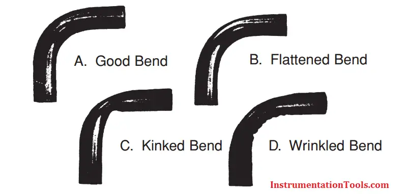
Common Causes of Imperfect Bends
Figure A shows an ideal bend. Bends with little or no flattening are produced when correct equipment and methods are employed; when proper consideration is given to co-relationship of the radius of the bend, material wall thickness and hardness of the tube.
Figure B shows a flattened bend, caused by trying to bend too short a radius, or bending smaller diameter tube in larger radius block.
Figure C shows a kinked and flattened bend, caused by the tube slipping in the bender, or by using non-annealed tubing. Tubes must be firmly clamped by clamp block to prevent slippage during bending process.
Figure D shows a wrinkled bend, sometimes produced when thin wall tube is bent. Breakage will sometimes occur when mandrel is too far forward in tube, or when too short a radius is attempts with hard tube.
Offset Bends
To form a tube offset, it is obviously necessary to make two bends. With these Parker hand tube benders, it is easy to make double 45° bends. To make an offset bend simply follow the “Offset Bend Allowance” steps below to determine the proper distance between the two 45° bends. Here’s the procedure.
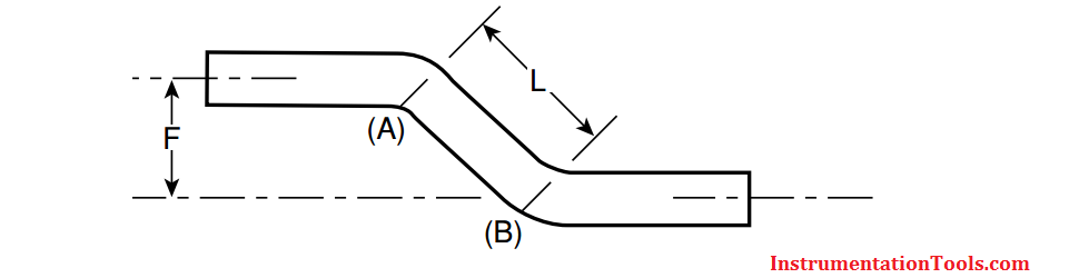
STEP 1 First, determine the total amount of offset required (dimension “F” in the diagram).
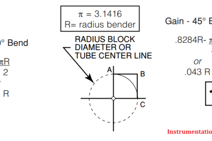
STEP 2 Next, determine the angle of offset – 30° or 45°. The latter (45°) is recommended because Parker hand benders are calibrated for 45° bending.
STEP 3 Figure the length of the tube required to meet your offset requirements (“L” dimension) in the diagram. For 30° bends multiply desired offset “F” x 2 = 30° offset dimension “L”. For 45° bends multiply desired offset “F” x 1.414 = 45° offset dimension “L”.
STEP 4 Determine where you want the offset bend of the tube to start; and make a reference mark (A). Now measure off the “L” dimension (determined in Step 3), starting from the reference mark and make a second mark (B). You are now ready to make the bends.
STEP 5 Align mark (A) with reference mark 45° on bender shoe handle (measurement end to the left) and proceed with first bend. Then align (B) with 45° mark and make second bend in proper direction (measurement end to the left). Follow previous detailed instructions for making 45° bends in one plane.
Routing of Bends
Routing of lines is probably the most difficult yet most significant of these system design considerations. Proper routing involves getting a connecting line from one point to another through the most logical path. The most logical path should:
Avoid excessive strain on joints – A strained joint will eventually leak
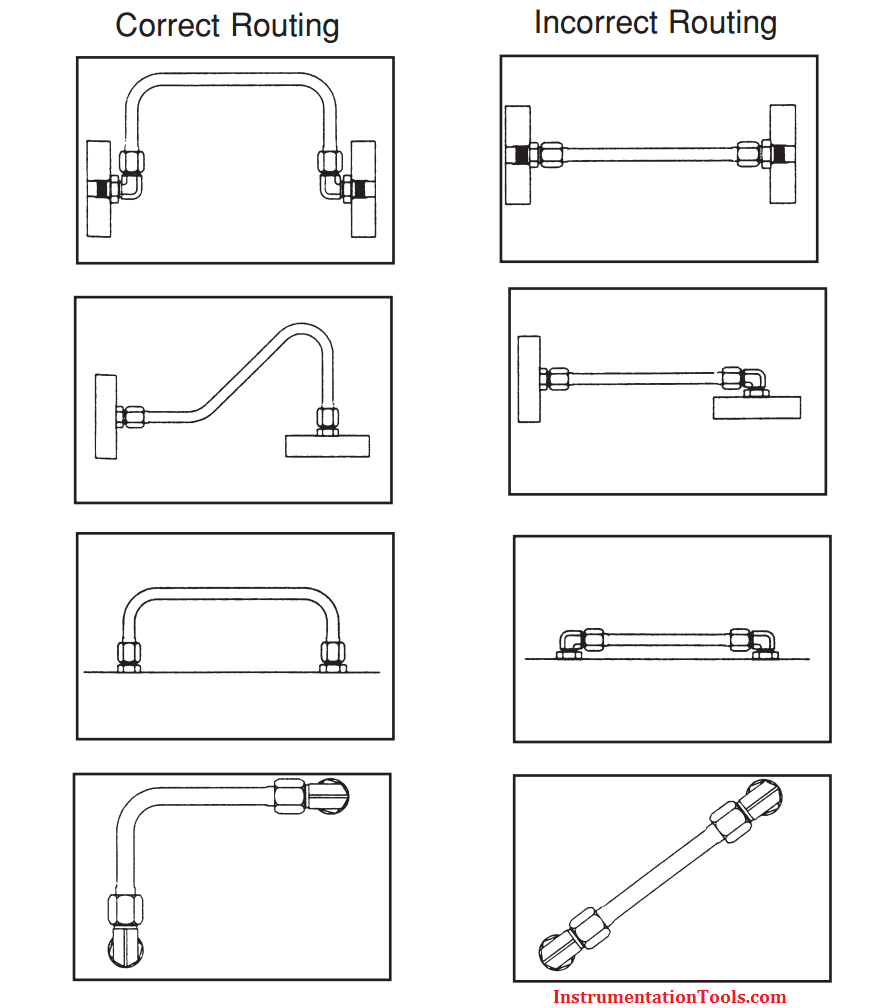
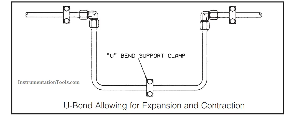
Allow for expansion and contraction – Use a “U” bend in long lines to allow for expansion and contraction.
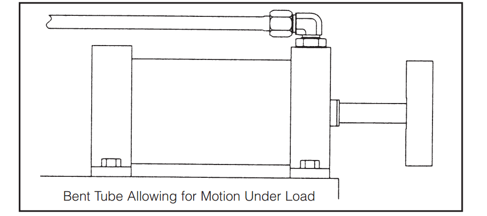
Allow for motion under load – Even some apparently rigid systems do move under load.
Get around obstructions without using excessive amount of 90° bends. Pressure drop due to one 90° bend is greater than that due to two 45° bends.
Get around obstructions without using excessive amount of 90° bends. Pressure drop due to one 90° bend is greater than that due to two 45° bends.
Keep tube lines away from components that require regular maintenance.
Have a neat appearance and allow for easy trouble shooting, maintenance and repair.
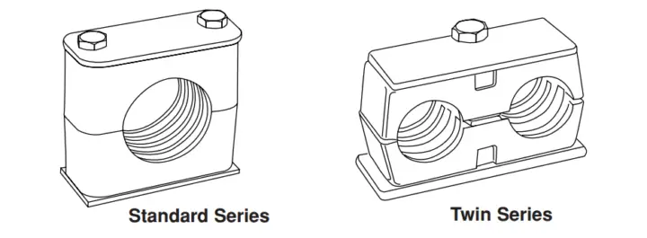
Tube Clamping
Once you’ve taken the time to make good bends and installed them, it’s not enough to just let them lay suspended in mid-air. When tubing is left unsupported, shock and vibration will cause the tubing to shake, and in turn, cause the fitting to loosen and leak or even allow tube to fall through fatigue.
Tube support and clamping is a necessary requirement in the fluid power industry. Tubing can be clamped individually, in sets, and can also be stacked. The most important part of any clamping system is having enough clamps to attain the final result. That being, a well supported, vibration and noise free system.
Also, most manufacturers specify SAE and JIC approved components on their equipment. The best way to meet these specs concerning clamps is to utilize a clamp that employs both an upper and lower unit made of metal and a rubber split bushing which surrounds the tube or pipe and fits on the inside of the clamping units.
Proper Tubing Selection
1. Always Match Materials –
I.E., S.S. Tubing should be used only with S.S. Fittings. The only exception to this rule is copper tubing with brass fittings. Mixing materials can cause galvanic corrosion.
Galvanic Corrosion (Electrochemical)
All metals have a specific relative electrical potential. When dissimilar metals come in contact in the presence of moisture (electrolyte), a low energy electric flows from the metal having the higher potential to the metal having the lower potential. The result of this galvanic action is the corrosion of the metal with the higher potential (more anodic)
2. Select proper tubing hardness – Remember Parker Instrumentation Tube Fittings are designed to work within specific hardness ranges. Rb 90 max. for S.S., Rb 80 recommended.
3. Select proper tubing wall thickness – Proper wall thickness is necessary to accommodate accepted safety factors relative to desired working pressures. For details on items 2 & 3 note “Instrumentation Tubing Selection Guide” shown on the following pages.
4. Tubing surface finish – Always select tubing free of visible drawmarks or surface scratches. If possible, cut off any undesirable sections. These “deep” scratches can cause leaks when attempting to seal low-density gases such as argon, nitrogen, or helium.
General Selection Criteria
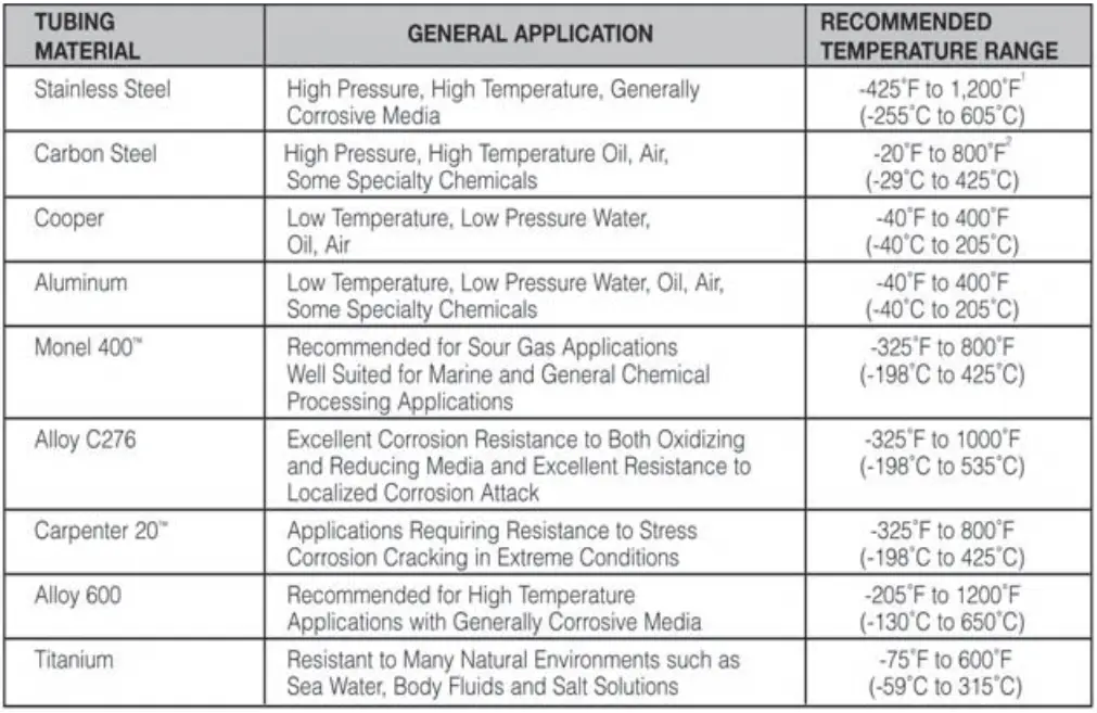
The most important consideration in the selection of suitable tubing for any application is the compatibility of the tubing material with the media to be contained. Table 1 lists common materials and their associated general application. Below Table also lists the maximum and minimum operating temperature for the various tubing materials.
In addition, Parker instrumentation fittings should be used only with stainless steel tubing, aluminum fittings with aluminum tubing, etc. The practice of mixing materials is strongly discouraged. The only exception is brass fittings with copper tubing.
Dissimilar materials in contact may be susceptible to galvanic corrosion. Further, different materials have different levels of hardness, and can adversely affect the fittings ability to seal on the tubing.
Carpenter 20 is a trademark of Carpenter Technology Corporation. Monel 400 is a trademark of International Nickel.
1. For operating temperatures above 800°F (425°C), consideration should be given to media. 300 Series Stainless Steels are suspectible to carbide precipitation which may lead to intergranular corrosion at elevated temperatures.
2. Consideration should be given to maximum temperature ratings if fittings and/or tubing are All temperature ratings based on temperatures per ASME/ANSI B31-3 Chemical Plant and Petroleum Refinery Piping Code, 1999 Edition.
Also Read: Tube Fitting Types