Inst ToolsInst ToolsInst Tools
  • Courses
  • Videos
  • Q & A
    • Interview
      • Instrumentation
      • Electronics
      • Electrical
      • Practical Questions
    • MCQ
      • Instrumentation MCQ
      • Electrical MCQ
      • Electronics MCQ
      • Control Systems MCQ
      • Analog Electronics MCQ
      • Digital Electronics MCQ
      • Power Electronics MCQ
      • Microprocessor MCQ
      • Multiple Choice Questions
  • EE
    • Electronics
      • Electronics Q & A
      • Electronic Basics
      • Electronic Devices & Circuits
      • Electronics Animation
      • Digital Electronics
    • Electrical
      • Electrical Basics
      • Electrical Q & A
      • Power Electronics
      • Electrical Machines
      • Electrical Animation
      • Power Systems
      • Switchgear & Protection
      • Transmission & Distribution
  • Measure
    • Control Valves
    • Calibration
    • Temperature
    • Pressure
    • Flow
    • Level
    • Analyzers
    • Switches
    • Vibration
    • Solenoid Valve
  • Control
    • PLC Tutorials
    • Control Systems
    • Safety Instrumented System (SIS)
    • Communication
    • Fire & Gas System
  • More
    • Design
    • Tools
    • Animation
    • Basics
    • Formulas
    • Standards
    • TextBooks
    • Common
    • Software
    • Excel Tools
    • Erection & Commissioning
    • Process Fundamentals
    • Videos
    • Books
Search
All rights reserved. Reproduction in whole or in part without written permission is prohibited.
Reading: Impulse Tubing Leak Test Checks
Share
Notification Show More
Font ResizerAa
Inst ToolsInst Tools
Font ResizerAa
  • Courses
  • PLC Tutorials
  • Control Systems
Search
  • Courses
  • Videos
  • Q & A
    • Interview
    • MCQ
  • EE
    • Electronics
    • Electrical
  • Measure
    • Control Valves
    • Calibration
    • Temperature
    • Pressure
    • Flow
    • Level
    • Analyzers
    • Switches
    • Vibration
    • Solenoid Valve
  • Control
    • PLC Tutorials
    • Control Systems
    • Safety Instrumented System (SIS)
    • Communication
    • Fire & Gas System
  • More
    • Design
    • Tools
    • Animation
    • Basics
    • Formulas
    • Standards
    • TextBooks
    • Common
    • Software
    • Excel Tools
    • Erection & Commissioning
    • Process Fundamentals
    • Videos
    • Books
Follow US
All rights reserved. Reproduction in whole or in part without written permission is prohibited.
Inst Tools > Blog > Erection & Commissioning > Impulse Tubing Leak Test Checks

Impulse Tubing Leak Test Checks

Discuss the various checks that need to be performed in the field during the impulse tubing leak test by instrument engineer.

Last updated: May 12, 2022 12:05 am
Editorial Staff
Erection & Commissioning
No Comments
Share
7 Min Read
SHARE

Leak Test Checks

The following checks need to be carried out prior to the Pressure test:

Contents
Leak Test ChecksImpulse Tubing TestStep1: Testing of Impulse lineStep 2: Taking Transmitter in Line

1. Check physical tapping correctness with respect to P&ID, hook-up diagrams.

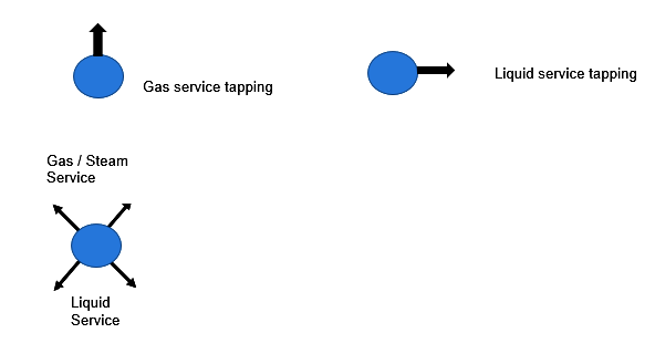
2. Check tapping orientation based on service and application.

impulse pipe leak test procedure

3. Check for correctness of installation of applicable element eg orifice (check direction) / Pitot tube / annubar (check direction), etc.

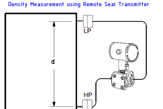
4. Check for HP (+) and LP (-) and trace if the impulse tube/pipe is correctly connected to the right port of transmitter from the flow element,

5. Verify installation with respect to hook-up,

6. Ensure that impulse lines are laid without any stress on tubes,

7. MOC of tubes, Pipes & Fittings to be checked using PMI test,

8. Check that ferrules are correctly punched in each and every fitting using GO / NO-GO gauge.

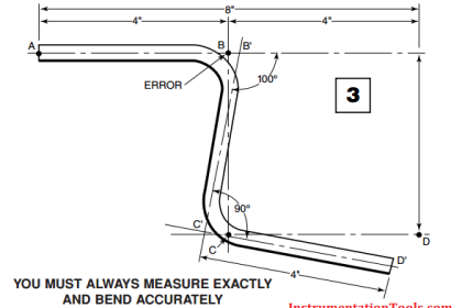
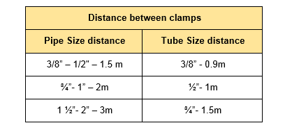
9. Impulse lines shall be supported and slope maintained properly.

Impulse lines distance

Polypropylene (PP) – -30 deg C to 90 deg C

Aluminium (Al)- -55 deg C to 260 deg C

Slope: 80 mm per meter as shown in hook-up

10. Check for tightness of support. Ensure these are not loose and rusted,

11. During and after installation all the Tubes are to be properly cleaned by using compressed air.

12. Check that all connections are done properly with GO / NO GO Gauge.

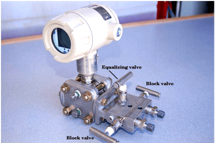
13. Ensure that instrument connected is isolated by closing the isolation valve of the Manifold and keeping the equalizing valve open. Also, the vent/drain of the transmitter to be kept open.

14. Ensure that the first process isolation valve is closed & the drain valves are closed

15. In differential pressure instruments ensure that the equalizing valve is open.

16. The test medium shall be as per requirements of a specification or unless specified otherwise.

17. Ensure two pressure gauges with valid calibrated certificates are used within the range of 1.5 times to 4 times of test pressure.

18. Instruments valid calibration, certificate & sticker on the gauge shall be verified.

19. The Test Pressure shall be 1.5 times of the process design pressure in case of Hydro Test or the Test pressure of the associated process line or vessel, whichever is greater, as specified in.

In the case of the pneumatic test, the Test pressure shall be 1.1 times. Please refer to the Line Designation table for test pressure.

20. Prior to filling the line with test medium, the line shall be inspected for fabrication and erection completeness and satisfactory test preparation.

21. All Quality records pertaining to the line shall be prepared and all these signed off records are to be compiled in a test pack.

This includes

  • Line History Sheet (Weld clearance reports),
  • Line clearance for the Pressure test,
  • PMI to be completed before the hydro test.
  • Internal cleanliness / Flushing of the Pipeline,
  • The test medium shall be checked for chloride content, before the hydro test.
  • Gauge calibration reports.
  • Hydro test report

22. After verifying the completeness of all the above applicable records line shall be cleared for the Pressure test.

Impulse Tubing Test

Liquid Test medium if applicable shall be introduced into the line at a low point to avoid air pocket formation.

Vents at high points shall be left open and not closed until clean Test medium flow from the outlet.

Impulse Tubing Leak Test Checks

Step1: Testing of Impulse line

Please Ensure positive isolation of the Instrument by closing the isolation valve(s) of the manifold.

After closing all vent and drain points Pressurize the line to specified test pressure and hold for a minimum period of 30 minutes for Hydro test, 10 minutes for Pneumatic Test as specified in Specification, or otherwise hold until all joints/connections are inspected for leaks, whichever is higher.

Step 2: Taking Transmitter in Line

To ensure overall integrity. When test pressure is below 80 kg/cm2. (or as per your application)

Ensure the opening of the equalizing valve and then only open the isolation valve(s) of the manifold and take the transmitter in line for 5 minutes and check the leakage.

Note:  When test pressure is above 80 Kg/cm2: the transmitter is to be taken in line after getting clearance from the Client and test pressure to be decided accordingly.

If leaks are observed in the line, mark these leaks and depressurize the line.

Before starting weld repairs, ensure that the lines shall be drained properly and weld repairs have been carried out with approved weld repair procedure. If any such repairs have been carried out, that line shall be Re-pressure tested and documented.

Depressurization of the line shall be carried out in a controlled manner. Instantaneous release of pressure is not permitted. These lines are to be drained out and air flushed after testing.

In the case of Test medium is Air / Nitrogen, flushing is not required unless specified otherwise.

For the ASU (Air Separation Unit):

  • The use of water for pressure testing is not permitted in O2 service and in enhanced cleanliness service. Therefore, in order to avoid any mistakes, prefer to use Dry Air / Nitrogen in general for all cases.
  • N2 / Air must be free of oil. Compressed medium from cylinders will be OK, but in the case of portable compressors, it may be difficult to control the content of oil/ moisture in the compressed medium.
  • Before the pressure test, the lines should be flushed with the above-mentioned test medium so as to remove all metallic particles in the tubes.
  • Safety precautions need to be arranged while using compressed air or N2 at high pressure.
Read Next:
  • Impulse Piping Field instruments
  • Gas Detectors Installation
  • Instrumentation Bulk Material
  • Instrumentation Steam Blowing
  • DCS Commissioning Steps
Don't Miss Our Updates
Be the first to get exclusive content straight to your email.
We promise not to spam you. You can unsubscribe at any time.
Invalid email address
You've successfully subscribed !

Recommended Articles

Important Factors Consider during Piping Design
Commissioning a Differential Pressure Transmitter in a Pressurized Boiler Steam Drum
P&ID Guidelines for Pumps
Magnetic Flow Meters Installation Guidelines
Flow Meter Installation Guidelines
P&ID Guidelines for Centrifugal Compressor Systems
Share This Article
Facebook Whatsapp Whatsapp LinkedIn Copy Link
Share
Leave a Comment

Leave a Reply Cancel reply

Your email address will not be published. Required fields are marked *

Stay Connected

128.3kFollowersLike
69.1kFollowersFollow
208kSubscribersSubscribe
38kFollowersFollow

Categories

Recent Comments

  • William Snyder on Top Non-PLC Certification Courses for Automation Professionals
  • Kamli on Top Free PLC Software
  • Guifty Shimica on Top Non-PLC Certification Courses for Automation Professionals
  • Guifty Shimica on Top Non-PLC Certification Courses for Automation Professionals

Related Articles

P&ID Guidelines for Pumps Heat Exchangers

P&ID Guidelines for Pumps Heat Exchangers

Basics of Ground Loops

Basics of Ground Loops

5-valve manifold

Pressure Transmitter Vent fittings

Good and Bad Wiring Practices

P&ID arrangement for Pressure Safety Valves

P&ID Guidelines for Pressure Safety Valves

What is Instrument Air Manifold

What is Instrument Air Manifold ?

Multiple Thermowell Installations Problems

Multiple Thermowell Installations Problems

Common Causes of Imperfect Bends

Instrument Tube Fitting Installation – Part 3

More Articles

Proximity Switch PNP Type Working Animation

Proximity switches Circuit Diagram Operation

Question on Remote Seal with Capillary Tubing Transmitter

Question on Remote Seal with Capillary Tubing Transmitter

Siemens S7 300 and STEP 7 PLC program using SIMATIC Software

Probe Type Radar Level Transmitter

Contact Type Guided Wave Radar Level Transmitter Working Principle

Power Triangle

Apparent Power, True Power, Reactive Power & Total Power

Basics-of-Gas-Chromatograph-Working-Principle

Working Principle of Gas chromatograph

Analog Electronics Objective Questions

Analog Electronics Objective Questions – Set 2

factorytalk view studio hmi

How to Create Templates in FactoryTalk View Studio?

Follow US
All rights reserved. Reproduction in whole or in part without written permission is prohibited.
Welcome Back!

Sign in to your account

Username or Email Address
Password

Lost your password?