Inst ToolsInst ToolsInst Tools
  • Courses
  • Automation
    • PLC
    • Control System
    • Safety System
    • Communication
    • Fire & Gas System
  • Instrumentation
    • Design
    • Pressure
    • Temperature
    • Flow
    • Level
    • Vibration
    • Analyzer
    • Control Valve
    • Switch
    • Calibration
    • Erection & Commissioning
  • Interview
    • Instrumentation
    • Electrical
    • Electronics
    • Practical
  • Q&A
    • Instrumentation
    • Control System
    • Electrical
    • Electronics
    • Analog Electronics
    • Digital Electronics
    • Power Electronics
    • Microprocessor
  • Request
Search
  • Books
  • Software
  • Projects
  • Process
  • Tools
  • Basics
  • Formula
  • Power Plant
  • Root Cause Analysis
  • Electrical Basics
  • Animation
  • Standards
  • 4-20 mA Course
  • Siemens PLC Course
Reading: Identify the Pressure Gauge Error
Share
Font ResizerAa
Inst ToolsInst Tools
Font ResizerAa
  • Courses
  • Design
  • PLC
  • Interview
  • Control System
Search
  • Courses
  • Automation
    • PLC
    • Control System
    • Safety System
    • Communication
    • Fire & Gas System
  • Instrumentation
    • Design
    • Pressure
    • Temperature
    • Flow
    • Level
    • Vibration
    • Analyzer
    • Control Valve
    • Switch
    • Calibration
    • Erection & Commissioning
  • Interview
    • Instrumentation
    • Electrical
    • Electronics
    • Practical
  • Q&A
    • Instrumentation
    • Control System
    • Electrical
    • Electronics
    • Analog Electronics
    • Digital Electronics
    • Power Electronics
    • Microprocessor
  • Request
Follow US
All rights reserved. Reproduction in whole or in part without written permission is prohibited.
Inst Tools > Blog > Practical Questions > Identify the Pressure Gauge Error

Identify the Pressure Gauge Error

An operator claims pressure gauge is defective and needs to be replaced. The pressure controller and gauge readings are different.

Last updated: September 7, 2020 5:05 pm
Editorial Staff
Practical Questions Pressure Measurement
No Comments
Share
3 Min Read
SHARE

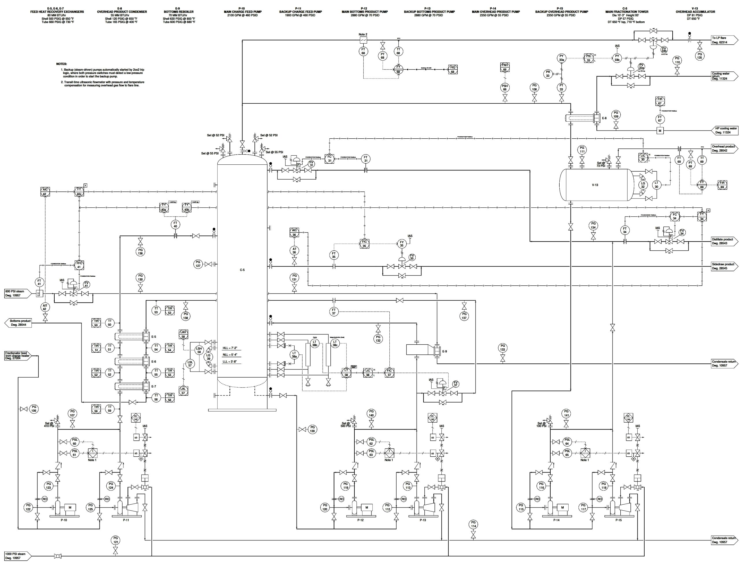
An operator claims pressure gauge PG-108 is defective and needs to be replaced. This pressure gauge registers 50 PSI, while pressure controller PIC-33 and pressure recorder PR-33 both register the pressure as being equal to setpoint: 43 PSI.

Before replacing this pressure gauge, however, you decide to do some diagnostic thinking to see if there might be other causes for the abnormally high reading at PG-108.

The first thing you check is the position of control valve PV-33a, and you find its stem position to be at 35% open.

Identify the Pressure Gauge Error

Identify the Pressure Gauge Error

Identify the likelihood of each specified fault in this process. Consider each fault one at a time (i.e. no coincidental faults), determining whether or not each fault could independently account for all measurements and symptoms in this process.

Identify the below faults are possible or impossible?

  • PG-108 calibration error
  • PT-33 calibration error
  • PIC-33 left in manual mode
  • PY-33a calibration error
  • PY-33b calibration error

Finally, identify the next diagnostic test or measurement you would make on this system. Explain how the result(s) of this next test or measurement help further identify the location and/or nature of the fault.

Answer:

The fact that the gauge disagrees with both the recorder and the controller tells us the problem is either with the gauge or with the transmitter. Nothing else (controller mode, valve signal path, PY-33a) could cause this to happen.

Therefore, valid tests include anything to help us discern whether there is a problem in the gauge, in the transmitter, in the resistor, or in the controller’s PV input.

  • PG-108 calibration error – Possible
  • PT-33 calibration error – Possible
  • PIC-33 left in manual mode – Impossible
  • PY-33a calibration error – Impossible
  • PY-33b calibration error – Impossible

More Questions:

  1. Based on the information you have at this point, can you tell whether any suspected calibration error is due to a misadjustment of zero or of span? Explain why or why not.
  2. Is controller PIC-33 direct-acting or reverse-acting? How can you tell?
  3. Does control valve PV-33a throttle gas or liquid? How can you tell?
  4. Identify a typographical error in this P&ID.
  5. A useful diagnostic technique for identifying which instrument is miscalibrated is to compare the readings of multiple instruments (all sensing the same process variable) to see which one of them disagrees most with the others. May we apply this technique to the problem at hand? If so, which instrument readings should we compare? If not, explain why not.

Share your answers with us through the below comments section.

Read Next:

  • Loop Diagram Questions
  • Faults in a Transformer
  • Control Loop Questions
  • Pressure Control Loop
  • Problem with Pirani Gauge

Credits: Tony R. Kuphaldt

Don't Miss Our Updates
Be the first to get exclusive content straight to your email.
We promise not to spam you. You can unsubscribe at any time.
Invalid email address
You've successfully subscribed !

Continue Reading

Draw Wiring of a Pressure Switch to control two lamps
What Effect on Hydrostatic Level Transmitter if Liquid Density Changes?
Pressure Detection Circuit
Pressure Transmitters Heat-traced impulse lines
Differential Pressure Transmitter Working Principle
Inspecting the Trends of PV and SP on a Process Chart Recorder
Share This Article
Facebook Whatsapp Whatsapp LinkedIn Copy Link
Share
Leave a Comment

Leave a Reply Cancel reply

Your email address will not be published. Required fields are marked *

Stay Connected

128.3kFollowersLike
69.1kFollowersFollow
210kSubscribersSubscribe
38kFollowersFollow

Categories

Explore More

Pneumatic Pressure Transmitters Principle
How much Pressure is applied to Inclined Water Manometer?
Solenoid Valves Questions & Answers – 1
Pressure Transmitter Troubleshooting Tips
Calculate Temperature of RTD
Pressure Gauges : Common Causes for Failures and Their Effective Solutions
Question on Analytical Controller
PLC connected to Three Pushbutton Switches

Keep Learning

Displacer Type Density Transmitter

Displacer Type Density Transmitter Question

Pressure Gauge Accessories

Pressure Gauge Accessories Questions and Answers

Pressure Transmitter Calibration Setup

Pressure Transmitter Preventive Maintenance

Closed Tank Liquid Level Measurement using Pressure Transmitter

Inferential Measurement based on Pressure

Calculation of Hydrostatic Pressure

Calculation of Hydrostatic Pressure

PLC Motor Control Circuit

Motor Trip Logic using PLC Programming

piping for a Different pressure flow transmitter

Impulse Piping standards for Field instruments

spiral bourdon tube

Bellows, Diaphragms and Bourdon Tubes

Learn More

Benefits of SIMOCODE over Intelligent MCC

Benefits of SIMOCODE over Intelligent MCC

Series-Wound DC Generator Principle

Series-Wound DC Generators

Multi-Tank Liquid Level Control System with Fill Priority [PLC]

Multi-Tank Liquid Level Control System with Fill Priority [PLC]

PLC Program using Counters

PLC Counters Program

VFD Block Diagram

What is a VFD? – Theory, Advantages, Disadvantages

Classification of valves

Losses in a DC Generator

kirchhoffs-voltage-law

What is Kirchhoff’s Voltage Law

Field Instrumentation Interview Questions and Answers

Field Instrumentation Interview Questions and Answers

Menu

  • About
  • Privacy Policy
  • Copyright

Quick Links

  • Learn PLC
  • Helping Hand
  • Part Time Job

YouTube Subscribe

Follow US
All rights reserved. Reproduction in whole or in part without written permission is prohibited.
Welcome Back!

Sign in to your account

Username or Email Address
Password

Lost your password?