Inst ToolsInst ToolsInst Tools
  • Courses
  • Automation
    • PLC
    • Control System
    • Safety System
    • Communication
    • Fire & Gas System
  • Instrumentation
    • Design
    • Pressure
    • Temperature
    • Flow
    • Level
    • Vibration
    • Analyzer
    • Control Valve
    • Switch
    • Calibration
    • Erection & Commissioning
  • Interview
    • Instrumentation
    • Electrical
    • Electronics
    • Practical
  • Q&A
    • Instrumentation
    • Control System
    • Electrical
    • Electronics
    • Analog Electronics
    • Digital Electronics
    • Power Electronics
    • Microprocessor
  • Request
Search
  • Books
  • Software
  • Projects
  • Process
  • Tools
  • Basics
  • Formula
  • Power Plant
  • Root Cause Analysis
  • Electrical Basics
  • Animation
  • Standards
  • 4-20 mA Course
  • Siemens PLC Course
Reading: Inferential Measurement based on Pressure
Share
Notification Show More
Font ResizerAa
Inst ToolsInst Tools
Font ResizerAa
  • Courses
  • Design
  • PLC
  • Interview
  • Control System
Search
  • Courses
  • Automation
    • PLC
    • Control System
    • Safety System
    • Communication
    • Fire & Gas System
  • Instrumentation
    • Design
    • Pressure
    • Temperature
    • Flow
    • Level
    • Vibration
    • Analyzer
    • Control Valve
    • Switch
    • Calibration
    • Erection & Commissioning
  • Interview
    • Instrumentation
    • Electrical
    • Electronics
    • Practical
  • Q&A
    • Instrumentation
    • Control System
    • Electrical
    • Electronics
    • Analog Electronics
    • Digital Electronics
    • Power Electronics
    • Microprocessor
  • Request
Follow US
All rights reserved. Reproduction in whole or in part without written permission is prohibited.
Inst Tools > Blog > Pressure Measurement > Inferential Measurement based on Pressure

Inferential Measurement based on Pressure

Last updated: February 11, 2019 10:49 am
Editorial Staff
Pressure Measurement
No Comments
Share
5 Min Read
SHARE

A very common technique in industrial instrumentation is to calculate the value of a process variable from the values of related variables which are easier to measure (Note 1 ) . As it so happens, there are a host of variables which one may infer from readings of differential pressure. This makes DP transmitters very versatile devices, not just limited to measuring process variables of pressure and vacuum. This portion of the book will explore some of the more common inferred measurements possible with DP instruments.

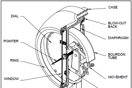
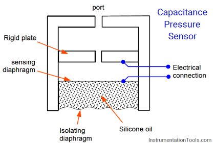
Note 1 : Truth be told, most process variables are inferred rather than directly measured. Even pressure, which is being used here to infer measurements such as liquid level and fluid flow, is itself inferred from some other variable inside the DP instrument (e.g. capacitance, strain gauge resistance, resonant frequency)!

Inferring liquid level

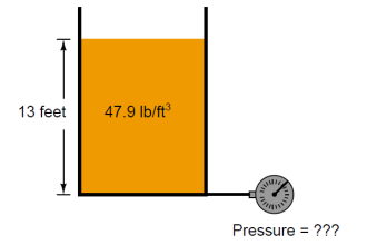
Liquids generate pressure proportional to height (depth) due to their weight. The pressure generated by a vertical column of liquid is proportional to the column height (h), and liquid’s mass density (ρ), and the acceleration of gravity (g):

P = ρgh

Knowing this, we may use a DP transmitter as a liquid level-sensing device if we know the density of the liquid remains fairly constant (We simply assume Earth’s gravitational acceleration (g) to be constant as well.)

Liquid Level Measurement using Pressure Transmitter

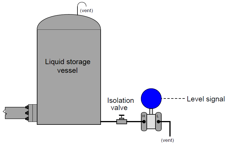
As liquid level in the vessel increases, the amount of hydrostatic pressure applied to the transmitter’s “high” port increases in direct proportion. The width of the vessel is irrelevant to the amount of pressure produced – only the liquid height (h), density (ρ), and Earth’s gravity (g) are significant. Thus, the transmitter’s increasing signal represents the height of liquid inside the vessel, no matter the size or shape of the vessel:

h = P / ρg

This simple technique works even if the vessel is under pressure from a gas or a vapor (rather than being vented as was the case in the previous example). All we need to do to compensate for this other pressure is to connect the DP transmitter’s “low” port to the top of the vessel so it senses nothing but the gas pressure:

Closed Tank Liquid Level Measurement using Pressure Transmitter

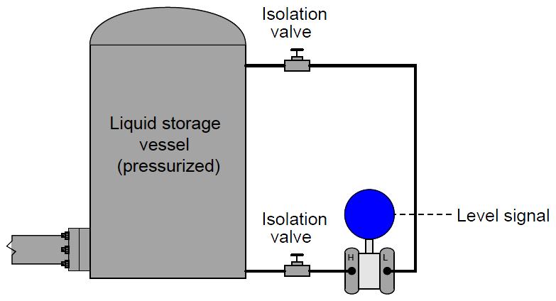
Since the transmitter responds only to differences of pressure between its two sensing ports, and the only cause for a difference of pressure in this application will be pressure generated by the height of a liquid column, the transmitter’s signal becomes an exclusive representation of liquid level in the vessel, rejecting potential measurement errors caused by changes in gas pressure within the vessel.

Any gas pressure within the vessel will be sensed equally by both ports on the transmitter as a “common-mode” pressure, thus canceling each other and having no effect on the differential pressure measurement. Only changes in liquid level within the vessel will cause the “high” port pressure to change independently of the “low” port pressure, changing the transmitter’s output signal.

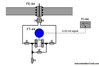
Inferring gas and liquid flow

Another common inferential measurement using DP transmitters is the measurement of fluid flow through a pipe. Pressure dropped across a constriction in the pipe varies in relation to flow rate (Q) and fluid density (ρ). So long as fluid density remains fairly constant, we may measure pressure drop across a piping constriction and use that measurement to infer flow rate.

The most common form of constriction used for this purpose is called an orifice plate, being nothing more than a metal plate with a precisely machined hole in the center. As fluid passes through this hole, its velocity changes, causing a pressure drop to form:

Orifice Plate

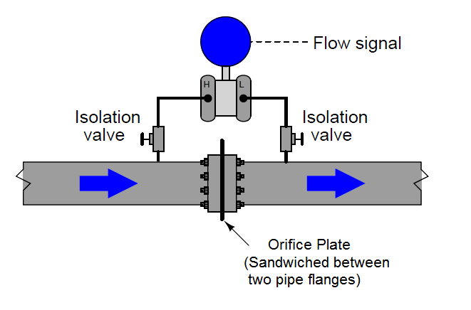
Once again, we see the common-mode rejection abilities of the pressure transmitter used for practical advantage. Since both ports of the transmitter connect to the same process line, static fluid pressure within that line has no effect on the measurement. Only differences of pressure between the upstream and downstream sides of the constriction (orifice plate) cause the transmitter to register flow.

 Credits : Tony R. Kuphaldt – Creative Commons Attribution 4.0 License

Don't Miss Our Updates
Be the first to get exclusive content straight to your email.
We promise not to spam you. You can unsubscribe at any time.
Invalid email address
You've successfully subscribed !

Continue Reading

Types of Manometers
Pneumatic Pressure Transmitters Principle
Troubleshooting Fluid Systems Pressure Changes
What is Static Pressure Limit in DP Transmitter ?
Pressure Gauges : Common Causes for Failures and Their Effective Solutions
Components of Bourdon Tube – Questions and Answers
Share This Article
Facebook Whatsapp Whatsapp LinkedIn Copy Link
Share
Leave a Comment

Leave a Reply Cancel reply

Your email address will not be published. Required fields are marked *

Stay Connected

128.3kFollowersLike
69.1kFollowersFollow
210kSubscribersSubscribe
38kFollowersFollow

Categories

Explore More

Types of Bourdon Tube
Pressure Measurement using Manometer
Differential Pressure Transmitter Calibration Procedure
Information on the Pressure Gauge Dial
Pressure Gauges : Remote and Chemical Seals
When to use a Diaphragm Seal?
Pressure Transmitters Filled impulse lines
Well Manometer Principle

Keep Learning

Gauge Cock

Pressure Gauge Cocks

Pressure Gauge Accessories

Pressure Gauge Accessories

Impulse Line Problems

What are Impulse Lines? – Impulse Line Problems & Solutions

inductance transducer

Inductance Type Pressure Transducers Principle

Top 30 Interview Questions on Pressure Measuring Devices

Top 30 Interview Questions on Pressure Measuring Devices

U tube Manometer Working

Basics of Pressure

5 Valve manifold

5 Valve Manifold Operation

pressure transmitter calibration setup

Questions on Pressure Transmitter Calibration Setup

Learn More

Asynchronous Motor Animation

Asynchronous Motor Animation

Ash Handling System in Thermal Power Plant

Ash Handling System in Thermal Power Plant

Formula of 2 Wire RTD, 3 Wire RTD & 4 Wire RTD

Formula of 2 Wire RTD, 3 Wire RTD & 4 Wire RTD

Working Principle of Overload Relay

Working Principle of Overload Relay

Thermocouples Green Rot Effect

Thermocouples Green Rot Effect

Magnetic Flow Meters

Magnetic Flow Meters Installation Guidelines

Case Statement in SCL Language

Case Statement in SCL Language

Electrical Machines Questions and Answers

Induction Motor as a Transformer

Menu

  • About
  • Privacy Policy
  • Copyright

Quick Links

  • Learn PLC
  • Helping Hand
  • Part Time Job

YouTube Subscribe

Follow US
All rights reserved. Reproduction in whole or in part without written permission is prohibited.
Welcome Back!

Sign in to your account

Username or Email Address
Password

Lost your password?