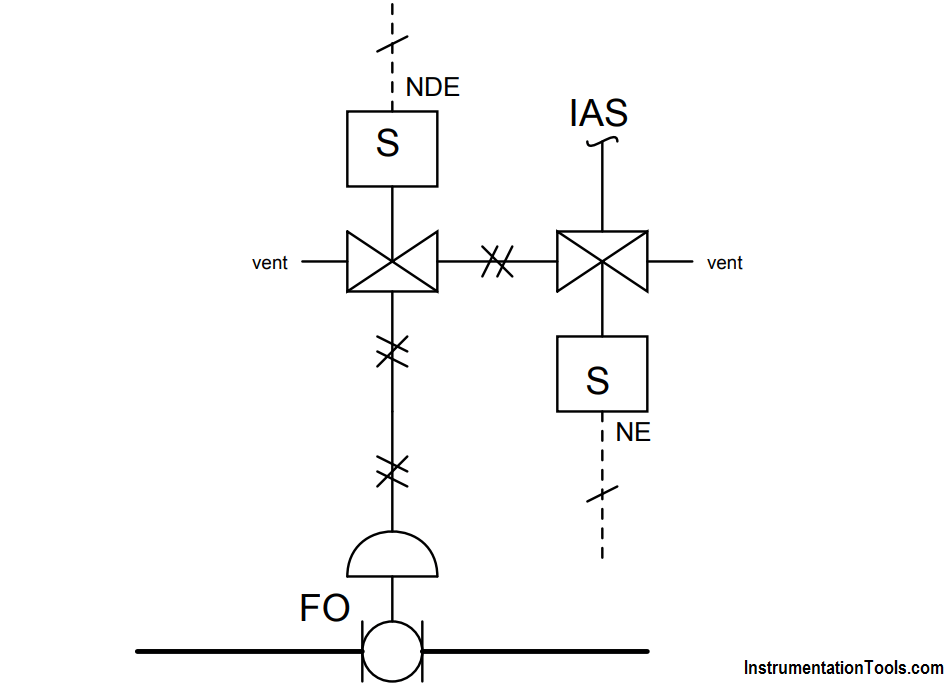
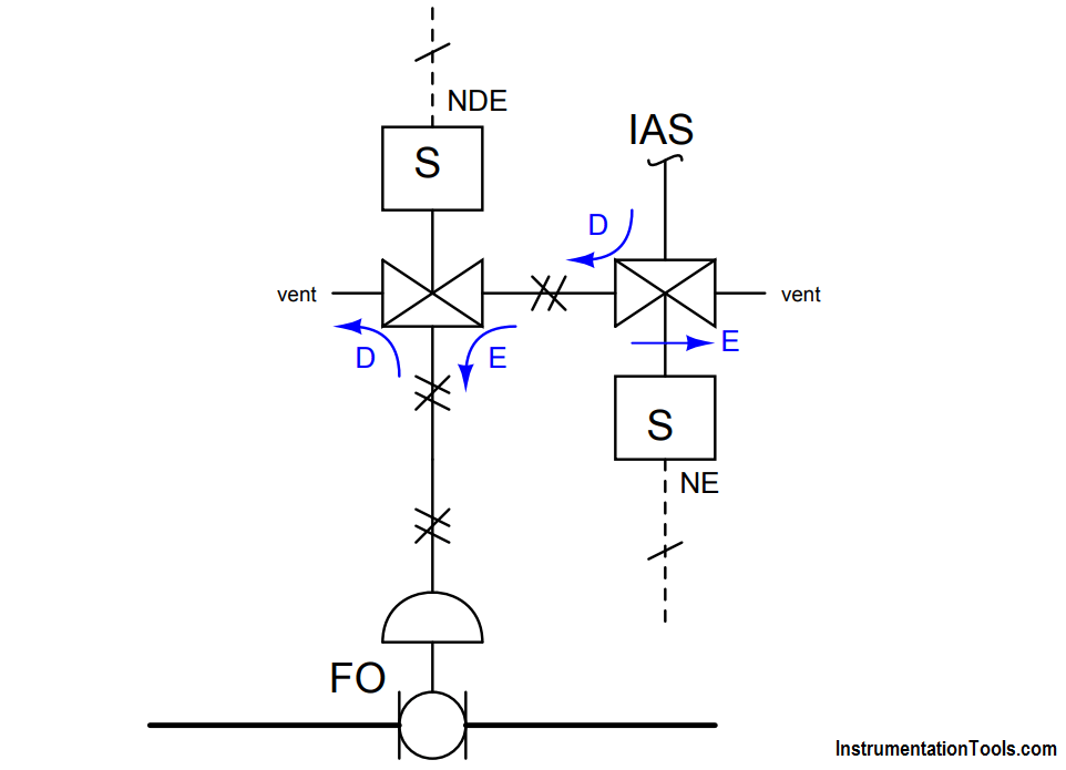
Sketch arrows next to each of the two solenoid valves showing the directions of air flow in the energized (E) and de-energized (D) states.
Assuming the process control valve is supposed to be open in regular operation and close if both of the solenoid valves “trip” (i.e. 2oo2 to trip):
Answer:

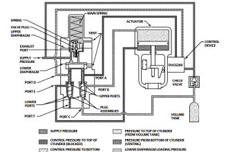

Is the Process control valve air fail open or air fail close??