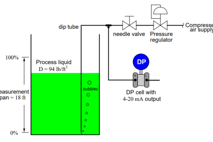
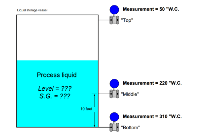
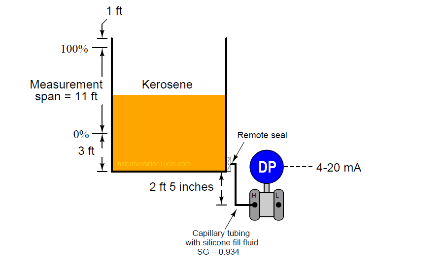
Calculate the proper LRV and URV pressures for the 4-20 mA loop-powered DP transmitter in this level measurement scenario:
Calculate LRV and URV
- LRV = inches water column
- URV = inches water column
Then, calculate the transmitter’s output given the following process levels (assuming perfect transmitter calibration):
Output = mA with the kerosene level 4 feet up from the bottom of the tank (4 feet “fillage”)
Output = mA with the kerosene level 6 feet down from the top of the tank (6 feet “ullage”)
Answer:
Note: a weight density (γ) of 51.2 lb/ft3 is assumed for kerosene.
LRV = 56.62 ”WC = 2.046 PSI
URV = 164.9 ”WC = 5.959 PSI
Output = 5.455 mA with the kerosene level 4 feet up from the bottom of the tank (4 feet “fillage”)
Output = 12.73 mA with the kerosene level 6 feet down from the top of the tank (6 feet “ullage”)
More Questions
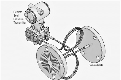
1. Suppose the DP transmitter with the remote seal failed and had to be replaced. Unfortunately, you don’t have another DP transmitter with a remote seal in stock to replace it. Could you use a DP transmitter without a remote seal for this application? If so, would its calibration have to be different from the remote-seal transmitter?
2. Explain why this installation does not require a compensating leg.
Share your answers with us through the below comments section.
Read Next:
- Pressure Gauge Dial
- Level Gauge Design
- Diaphragm Pressure Sensor
- Pneumatic Relay Questions
- Instrument Calibration Question
Credits: Tony R. Kuphaldt