Inst ToolsInst ToolsInst Tools
  • Courses
  • Automation
    • PLC
    • Control System
    • Safety System
    • Communication
    • Fire & Gas System
  • Instrumentation
    • Design
    • Pressure
    • Temperature
    • Flow
    • Level
    • Vibration
    • Analyzer
    • Control Valve
    • Switch
    • Calibration
    • Erection & Commissioning
  • Interview
    • Instrumentation
    • Electrical
    • Electronics
    • Practical
  • Q&A
    • Instrumentation
    • Control System
    • Electrical
    • Electronics
    • Analog Electronics
    • Digital Electronics
    • Power Electronics
    • Microprocessor
  • Request
Search
  • Books
  • Software
  • Projects
  • Process
  • Tools
  • Basics
  • Formula
  • Power Plant
  • Root Cause Analysis
  • Electrical Basics
  • Animation
  • Standards
  • 4-20 mA Course
  • Siemens PLC Course
Reading: Hydrostatic Level Transmitter Questions
Share
Notification Show More
Font ResizerAa
Inst ToolsInst Tools
Font ResizerAa
  • Courses
  • Design
  • PLC
  • Interview
  • Control System
Search
  • Courses
  • Automation
    • PLC
    • Control System
    • Safety System
    • Communication
    • Fire & Gas System
  • Instrumentation
    • Design
    • Pressure
    • Temperature
    • Flow
    • Level
    • Vibration
    • Analyzer
    • Control Valve
    • Switch
    • Calibration
    • Erection & Commissioning
  • Interview
    • Instrumentation
    • Electrical
    • Electronics
    • Practical
  • Q&A
    • Instrumentation
    • Control System
    • Electrical
    • Electronics
    • Analog Electronics
    • Digital Electronics
    • Power Electronics
    • Microprocessor
  • Request
Follow US
All rights reserved. Reproduction in whole or in part without written permission is prohibited.
Inst Tools > Blog > Practical Questions > Hydrostatic Level Transmitter Questions

Hydrostatic Level Transmitter Questions

Determine the lower and upper range values (LRV & URV) when installing a new hydrostatic level transmitter.

Last updated: November 18, 2020 12:11 pm
Editorial Staff
Practical Questions
1 Comment
Share
4 Min Read
SHARE

When installing a hydrostatic level transmitter on a working process, one must determine the proper lower- and upper-range values (LRV and URV) for the transmitter in order to properly register 0% at the LRV liquid level and 100% at the URV liquid level.

If all fluid densities and physical dimensions are known in advance, this is a simple matter of a few mathematical calculations.

However, sometimes it is difficult to know all the physical dimensions in advance, especially the elevation or suppression.

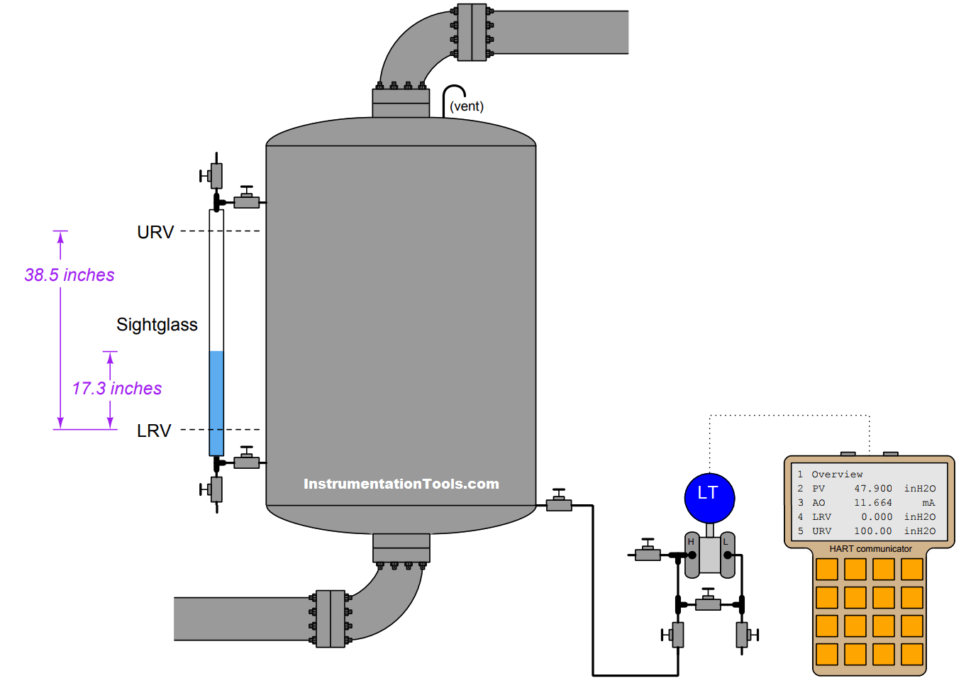
Consider this example, assuming clean water as the process liquid and a static pressure of 0 PSIG inside the (vented) process vessel:

Hydrostatic Level Transmitter
Hydrostatic Level Transmitter Questions

This transmitter has already been calibrated at the instrument shop to accurately register applied pressure, but its range values have not been customized to the installation. Using a tape measure, we find a vertical distance of 38.5 inches between the LRV and URV points marked on the sightglass, and we also see the current liquid level is 17.3 inches above the marked LRV point.

Also Read : Hydrostatic Level Measurement Basics

Using a HART communicator to interrogate this “smart” transmitter, we see that the registered pressure at this process condition is 47.9 inches of water column (”WC), which is greater than 17.3 inches registered by the sightglass due to the transmitter’s suppression (physical location beneath the LRV point, creating a hydrostatic pressure simply due to process water inside the impulse tube).

Based on this information alone, calculate the appropriate LRV and URV settings to program into the smart transmitter, so that it will output 4 mA when the process water level is at the LRV height and 20 mA when the water level is at the URV height:

LRV = _______”WC

URV = _______”WC

Answer :

If the transmitter registers an actual applied pressure of 47.9 ”WC when the process water level is known to be 17.3 inches above the LRV, it means the transmitter must be mounted 30.6 inches below that LRV height:

47.9 ”WC − 17.3 ”WC = 30.6 ”WC

This 30.6 inch suppression then becomes the transmitter’s lower-range value, so that it will output 4 mA (0% signal) when the process water level is at the LRV height and the only pressure sensed by the transmitter is the hydrostatic pressure produced by water inside the 30.6 vertical inches of impulse tube.

The necessary upper-range value is simply this LRV added to the known span of 38.5 inches:

30.6 ”WC + 38.5 ”WC = 69.1 ”WC

so final LRV & URV Values are :

LRV = 30.6 ”WC

URV = 69.1 ”WC

Share your answers and explanation with us through the below comments section.

Read Next:

  • Pressure Control Loop
  • Which Instrument is Faulty?
  • Loop Powered Transmitter
  • Instrument Ranging Tips
  • Tank Level Transmitter

Credits: Tony R. Kuphaldt
Don't Miss Our Updates
Be the first to get exclusive content straight to your email.
We promise not to spam you. You can unsubscribe at any time.
Invalid email address
You've successfully subscribed !

Continue Reading

Programmable Logic Controller (PLC) Questions and Answers – 14
Calculate Total Hydrostatic Pressure at Bottom of Vessel
Determine the Status of Lamps and Relays in the Circuit ?
DP Transmitter Calibration Errors
Practical Process Control System Questions & Answers – 3
Flow Transmitter Readings mismatch with DCS
Share This Article
Facebook Whatsapp Whatsapp LinkedIn Copy Link
Share
1 Comment
  • ABASAHEB BHANDARE says:
    January 6, 2020 at 10:23 pm

    Nice

    Reply

Leave a Reply Cancel reply

Your email address will not be published. Required fields are marked *

Stay Connected

128.3kFollowersLike
69.1kFollowersFollow
210kSubscribersSubscribe
38kFollowersFollow

Categories

Explore More

Float-type Level Switch for Sensing Low Oil Level
Solenoid-controlled Valve Problem
Calculate Hydraulic System Fluid Pressure
Calculate Density and Specific Gravity
How Manometer Measures Differential Pressure for Different Fluids?
Calculate Process Temperature using a Thermocouple
Pitot Tube Flowmeter Calculations
Calculate the Temperature of 4 Wire RTD

Keep Learning

Identify the Pressure Gauge Error

Identify the Pressure Gauge Error

float-type level switch control a pump

Float-type Level Switch to Control a pump

Which instrument is faulty

Which Instrument is Faulty? Transmitter, Recorder, or Controller

steadily pour a liquid into vertical tube

Vertical Tube Liquid Level Equilibrium

process conditions, Find out the Circuit Components Status

As per Process Conditions, Find out the Circuit Components Status ?

Calculate Amount of Weight Indicated by the Scale

Calculate Amount of Weight Indicated by the Scale

Foxboro pneumatic instruments

Pneumatic Force Balance Instrument

simulate a thermocouple

Calculate the appropriate millivoltage values of a Thermocouple

Learn More

Turbine Bypass System

Turbine Bypass System

pH and ORP eBook Download

pH and ORP Learning Handbook

Top PLC Manufacturers

PLC Brands Software Information

7 Marketing Strategies for Engineering Companies

7 Marketing Strategies for Engineering Companies

multiphase-flowmeter-working-principle

What are Multiphase Flow Meters? – Working Principle, Advantages

Metal tube Variable Area Flowmeters Principle

Metal Tube Variable Area Flow Meters Principle

Types of Transfomer Cooling Methods

Instrumentation Engineering Standards Interview Questions & Answers

Electrical Machines Objective Questions & Answers

Menu

  • About
  • Privacy Policy
  • Copyright

Quick Links

  • Learn PLC
  • Helping Hand
  • Part Time Job

YouTube Subscribe

Follow US
All rights reserved. Reproduction in whole or in part without written permission is prohibited.
Welcome Back!

Sign in to your account

Username or Email Address
Password

Lost your password?