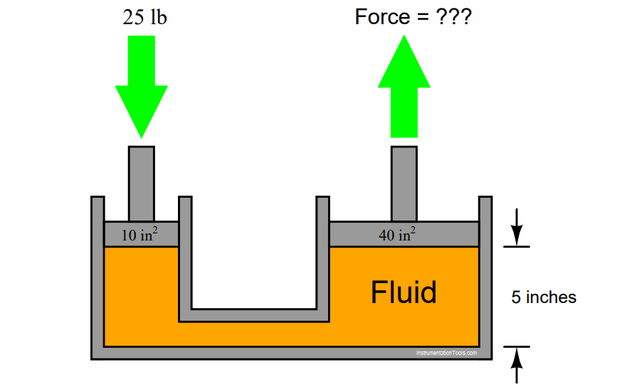
In this hydraulic system, a force of 25 pounds is applied to the small piston (area = 10 in2 ). How much force will be generated at the large piston (area = 40 in2 )?
Also, calculate the fluid’s pressure.
Hydraulic System Fluid Pressure
Finally, explain how Pascal’s Principle relates to this scenario.
Answer:
Force at large piston = 100 pounds. Fluid pressure = 2.5 PSI.
Pascal’s principle states that any pressure applied to a contained fluid will be experienced at all points throughout that fluid. Thus, pressure generated by the 25 lb of force on the small piston creates a pressure (2.5 PSI) distributed throughout the fluid’s volume which is experienced in full at the large piston to create the 100 lb force there.
The 5 inch dimension is extraneous information, included for the purpose of challenging students to identify whether or not information is relevant to solving a particular problem.
More Questions:
1. Identify which fundamental principles of science, technology, and/or math apply to each step of your solution to this problem. In other words, be prepared to explain the reason(s) “why” for every step of your solution, rather than merely describing those steps.
2. Identify a practical application for a hydraulic system such as this.
3. Does the pressure/force/area equation hold true for all piston positions, or only with the pistons in mid-stroke as shown in the illustration?
4. Would it matter whether the fluid in this system was a liquid or a gas? Explain in detail how the system’s behavior would differ (or not differ) depending on the type of fluid used.
5. This mechanism seems to multiply the applied force. How can it do so without violating the Law of Energy Conservation (energy out cannot exceed energy in)?
6. Demonstrate how to estimate numerical answers for this problem without using a calculator.
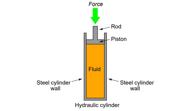
Hydraulic Cylinder Question 1
If force is exerted on the piston of this hydraulic cylinder, in what direction(s) will this force be transmitted to the cylinder walls? In other words, how does a fluid under pressure push against its surrounding container?
Answer:
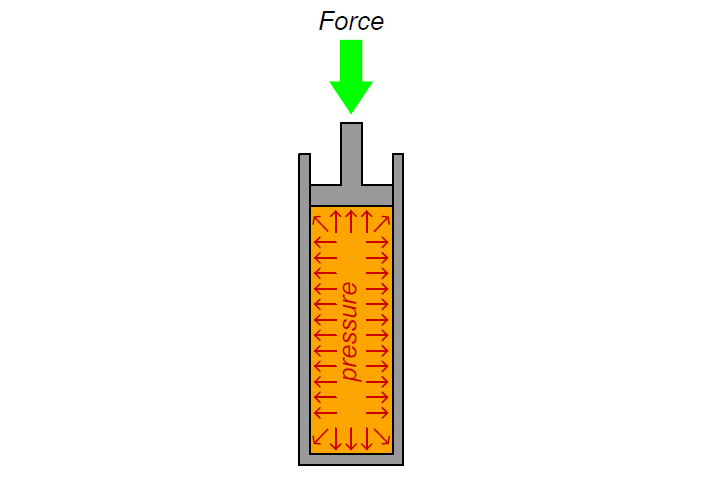
The fluid pressure will exert an outward force on the cylinder walls, like this:
Hydraulic Cylinder Question 2
Suppose a small rubber ball is floating inside the fluid of a hydraulic cylinder as shown below. What will happen to the ball when a pushing force is exerted on the cylinder’s rod? What will happen to the ball when a pulling force is exerted on the rod?
Answer:
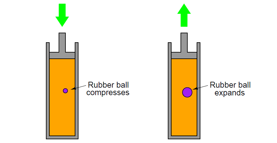
A pushing force on the rod will compress the rubber ball to a smaller diameter. A pulling force will expand it to a larger diameter.
Hydraulic Cylinder Question 3
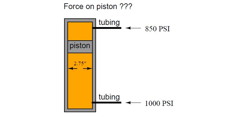
A free-floating piston inside a hydraulic cylinder has a 1000 PSI of fluid pressure applied to one side of the piston, and 850 PSI of pressure applied to the other side of the piston. The piston itself is 2.75 inches in diameter. How much force will act on the piston, with these pressures applied to it?
Answer:
Net piston force = 890.936 pounds.
In this scenario, there are two pressures fighting against each other: the 850 PSI pressure is pressing downward on the piston while the 1000 PSI pressure is pressing upward. The resultant (differential) pressure is 150 PSI (1000 PSI – 850 PSI). This is the pressure figure to be used in the final force calculation.
Hydraulic Cylinder Question 4
A double-acting hydraulic cylinder has 500 PSI of pressure applied to the side without the rod and 750 PSI of pressure applied to the rod-side. Calculate the resultant force generated at the piston and transmitted through to the rod, and also determine this force’s direction. The piston is 5 inches in diameter, and the rod is 1 inch in diameter.
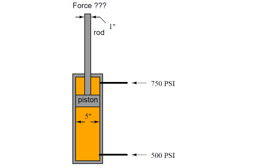
Answer:
Net force = 4,319.69 pounds, in the downward direction.
If your calculated force turned out to be 4,908.7 pounds, you made a very common error. Once you have figured out what this error is, go back and try to see how the scenario would have to be altered in order to actually generate 4,908.7 pounds of force with the two pressures being 750 PSI and 500 PSI, respectively.
Read Next:
- Live Zero in 4-20 mA Loop
- Why we Tune a PID Controller?
- 4-20 mA Formula
- Compare Fieldbus & 4-20 mA
- Control Loop Testing