Inst ToolsInst ToolsInst Tools
  • Courses
  • Automation
    • PLC
    • Control System
    • Safety System
    • Communication
    • Fire & Gas System
  • Instrumentation
    • Design
    • Pressure
    • Temperature
    • Flow
    • Level
    • Vibration
    • Analyzer
    • Control Valve
    • Switch
    • Calibration
    • Erection & Commissioning
  • Interview
    • Instrumentation
    • Electrical
    • Electronics
    • Practical
  • Q&A
    • Instrumentation
    • Control System
    • Electrical
    • Electronics
    • Analog Electronics
    • Digital Electronics
    • Power Electronics
    • Microprocessor
  • Request
Search
  • Books
  • Software
  • Projects
  • Process
  • Tools
  • Basics
  • Formula
  • Power Plant
  • Root Cause Analysis
  • Electrical Basics
  • Animation
  • Standards
  • 4-20 mA Course
  • Siemens PLC Course
Reading: Guided-wave Radar Level Measurement Animation
Share
Font ResizerAa
Inst ToolsInst Tools
Font ResizerAa
  • Courses
  • Design
  • PLC
  • Interview
  • Control System
Search
  • Courses
  • Automation
    • PLC
    • Control System
    • Safety System
    • Communication
    • Fire & Gas System
  • Instrumentation
    • Design
    • Pressure
    • Temperature
    • Flow
    • Level
    • Vibration
    • Analyzer
    • Control Valve
    • Switch
    • Calibration
    • Erection & Commissioning
  • Interview
    • Instrumentation
    • Electrical
    • Electronics
    • Practical
  • Q&A
    • Instrumentation
    • Control System
    • Electrical
    • Electronics
    • Analog Electronics
    • Digital Electronics
    • Power Electronics
    • Microprocessor
  • Request
Follow US
All rights reserved. Reproduction in whole or in part without written permission is prohibited.
Inst Tools > Blog > Animation > Guided-wave Radar Level Measurement Animation

Guided-wave Radar Level Measurement Animation

Last updated: March 30, 2019 12:21 pm
Editorial Staff
Animation Level Measurement
4 Comments
Share
0 Min Read
SHARE

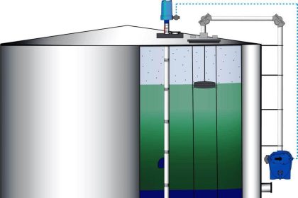
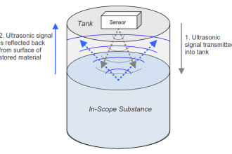
The following animation shows how a radio-energy pulse travels down and then up the wave guide of a guided-wave radar level instrument, relating the peaks on an echo curve to the real-world interfaces inside the process vessel.

Guided-wave Radar Level Measurement

Guided-wave radar level measurement Animation

Read : Radar Level Measurement Principle

Don't Miss Our Updates
Be the first to get exclusive content straight to your email.
We promise not to spam you. You can unsubscribe at any time.
Invalid email address
You've successfully subscribed !

Continue Reading

Closed tank DP Level Transmitter with cleaning leg Calibration
Relay Working Animation
Comparison of Level Meters – Level Measurement Instruments
Eddy Current Working Principle Animation
Radar Level Transmitter in Briddle level Measurement
Flare Knockout Drums Working Animation
Share This Article
Facebook Whatsapp Whatsapp LinkedIn Copy Link
Share
4 Comments
  • Naresh J says:
    December 12, 2017 at 6:11 pm

    Excellent Animation. Very useful. Thanks

    Reply
  • David Shin says:
    April 26, 2018 at 6:20 am

    Simple and perfect animation to understand GWR.

    Reply
  • adil naiym says:
    November 14, 2019 at 5:38 pm

    thank you so much

    Reply
  • Dim_DIM says:
    September 27, 2020 at 8:38 pm

    makasih mas bro.

    Reply

Leave a Reply Cancel reply

Your email address will not be published. Required fields are marked *

Stay Connected

128.3kFollowersLike
69.1kFollowersFollow
210kSubscribersSubscribe
38kFollowersFollow

Categories

Explore More

Dead Weight Tester Working Animation
Conductive Level Measurement Working Principle
Area Velocity Flow Meter Principle
Level Transmitter Calibration Procedure
Magnetic Float Level Transmitter Working Principle
Normally-open and Normally-closed Switch Contacts
How a 4-20mA Transmitter Works?
PID Controller Gains Effect on Manipulated Variable

Keep Learning

Displacer Level Sensor Working Animation

Displacer Level Sensor Working Animation

Turbine Flow Meters Working Animation

Turbine Flow Meters Animation

DP-Level-Transmitter-Diaphragm-with-capillary-tube-type

DP Level Transmitter Calibration for Diaphragm Seal with Capillary

Capacitive Tank Gauges

Capacitive Tank Gauges

Differential Pressure Transmitter Wet Leg Compensation

Differential Pressure Transmitters Compensated Leg Systems

capacitance probe

Capacitance Level Measurement Working Principle

Paddle Type Level Switch

What is a Level Switch? Types of Level Switches

Ultrasonic Level Measurement Questions and Answers

Ultrasonic Level Measurement Questions and Answers

Learn More

DP type Flow Transmitter Preventive Maintenance

Troubleshooting DP type Transmitter Common Problems

Instrumentation Basics - Range Conversion Formula and Examples

Instrumentation Basics – Range Conversion Formula and Examples

Profibus DP Master

DP Master System Configuration in PLC

Two Electrode Conductivity Probes

Two Electrode Conductivity Probes Principle

Shift Registers and Counters Objective Questions

Shift Registers and Counters Objective Questions

RF Capacitance Switch Principle

Safety Switches for Controlling Conveyor Operations

Single-beam non-dispersive analyzer

Single-beam Non-dispersive Analyzer

Valve Safety Factor

Valve Safety Factor

Menu

  • About
  • Privacy Policy
  • Copyright

Quick Links

  • Learn PLC
  • Helping Hand
  • Part Time Job

YouTube Subscribe

Follow US
All rights reserved. Reproduction in whole or in part without written permission is prohibited.
Welcome Back!

Sign in to your account

Username or Email Address
Password

Lost your password?