Inst ToolsInst ToolsInst Tools
  • Courses
  • Automation
    • PLC
    • Control System
    • Safety System
    • Communication
    • Fire & Gas System
  • Instrumentation
    • Design
    • Pressure
    • Temperature
    • Flow
    • Level
    • Vibration
    • Analyzer
    • Control Valve
    • Switch
    • Calibration
    • Erection & Commissioning
  • Interview
    • Instrumentation
    • Electrical
    • Electronics
    • Practical
  • Q&A
    • Instrumentation
    • Control System
    • Electrical
    • Electronics
    • Analog Electronics
    • Digital Electronics
    • Power Electronics
    • Microprocessor
  • Request
Search
  • Books
  • Software
  • Projects
  • Process
  • Tools
  • Basics
  • Formula
  • Power Plant
  • Root Cause Analysis
  • Electrical Basics
  • Animation
  • Standards
  • 4-20 mA Course
  • Siemens PLC Course
Reading: Stepper Motor Working Principle
Share
Notification Show More
Font ResizerAa
Inst ToolsInst Tools
Font ResizerAa
  • Courses
  • Design
  • PLC
  • Interview
  • Control System
Search
  • Courses
  • Automation
    • PLC
    • Control System
    • Safety System
    • Communication
    • Fire & Gas System
  • Instrumentation
    • Design
    • Pressure
    • Temperature
    • Flow
    • Level
    • Vibration
    • Analyzer
    • Control Valve
    • Switch
    • Calibration
    • Erection & Commissioning
  • Interview
    • Instrumentation
    • Electrical
    • Electronics
    • Practical
  • Q&A
    • Instrumentation
    • Control System
    • Electrical
    • Electronics
    • Analog Electronics
    • Digital Electronics
    • Power Electronics
    • Microprocessor
  • Request
Follow US
All rights reserved. Reproduction in whole or in part without written permission is prohibited.
Inst Tools > Blog > Animation > Stepper Motor Working Principle

Stepper Motor Working Principle

Last updated: February 9, 2019 10:31 am
Editorial Staff
Animation Electrical Basics
1 Comment
Share
3 Min Read
SHARE

Stepper motors are DC motors that move in discrete steps. They have multiple coils that are organized in groups called “phases”. By energizing each phase in sequence, the motor will rotate, one step at a time.

With a computer controlled stepping you can achieve very precise positioning and/or speed control. For this reason, stepper motors are the motor of choice for many precision motion control applications.
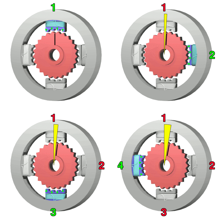
stepper motors Animation

Stepper Motor Operation

In this theory section, we’ll get a quick reminder about how stepper motor works. Stepper motors work in very specific way, a standard stepper motor will have two or more coils that charge and discharge when electricity is allowed to flow through them. The animation below illustrates that.
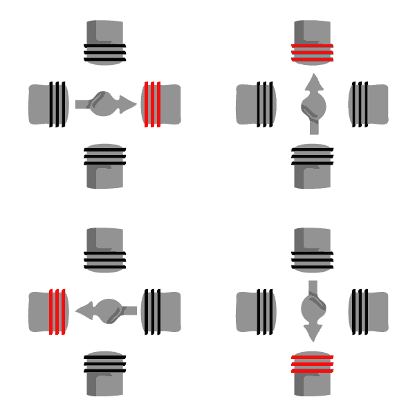
Stepper Motor Working Principle Animation

When the coils are charged and discharged in a specific pattern (usually sequentially), it creates an electromagnetic attraction between the coil and the motor. When this occurs fast enough it makes the stepper motor turn, and we get the movement you see above.

Advantages of Stepper Motor

  • Positioning – Since steppers move in precise repeatable steps, they excel in applications requiring precise positioning such as 3D printers, CNC, Camera platforms and X,Y Plotters. Some disk drives also use stepper motors to position the read/write head.
  • Speed Control – Precise increments of movement also allow for excellent control of rotational speed for process automation and robotics.
  • Low Speed Torque – Normal DC motors don’t have very much torque at low speeds. A Stepper motor has maximum torque at low speeds, so they are a good choice for applications requiring low speed with high precision.

Disadvantages of Stepper Motor

  • Low Efficiency – Unlike DC motors, stepper motor current consumption is independent of load. They draw the most current when they are doing no work at all. Because of this, they tend to run hot.
  • Limited High Speed Torque – In general, stepper motors have less torque at high speeds than at low speeds. Some steppers are optimized for better high-speed performance, but they need to be paired with an appropriate driver to achieve that performance.
  • No Feedback – Unlike servo motors, most steppers do not have integral feedback for position. Although great precision can be achieved running ‘open loop’. Limit switches or ‘home’ detectors are typically required for safety and/or to establish a reference position.
Don't Miss Our Updates
Be the first to get exclusive content straight to your email.
We promise not to spam you. You can unsubscribe at any time.
Invalid email address
You've successfully subscribed !

Continue Reading

Design and Implement Motor Control – Electrical Engineering
Electrical Switches Working Animation
What is a Line Choke or Reactor in a VFD?
Difference Between Core and Shell Transformers
Motor VFD Drive features
Understanding Protection Relays – 50, 50N, 51, 51N
Share This Article
Facebook Whatsapp Whatsapp LinkedIn Copy Link
Share
1 Comment
  • Anantharaman says:
    November 2, 2016 at 11:31 am

    its very nice and million thanks for your work .

    Reply

Leave a Reply Cancel reply

Your email address will not be published. Required fields are marked *

Stay Connected

128.3kFollowersLike
69.1kFollowersFollow
210kSubscribersSubscribe
38kFollowersFollow

Categories

Explore More

Technical Specification for Uninterrupted Power Supply (UPS) System
VFD Pros and Cons – Variable Frequency Drives
Float Level Switch Working Principle Animation
Types of MCB
Ultrasonic Flow Meters Animation
Industrial Circuit Breakers – Most Common Types – Principle
What is a Lightning Arrester? How does it work?
Dome Valve Working Principle

Keep Learning

VFD Braking

DC Injection Braking in VFD

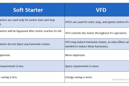
Difference between Soft Starter and VFD

Difference between Soft Starter and VFD

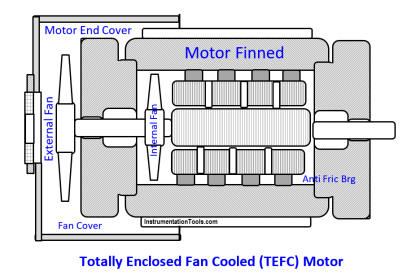
Totally Enclosed Fan Cooled (TEFC) Motor

Totally Enclosed Fan Cooled (TEFC) Motors Rampant Winding Burnouts

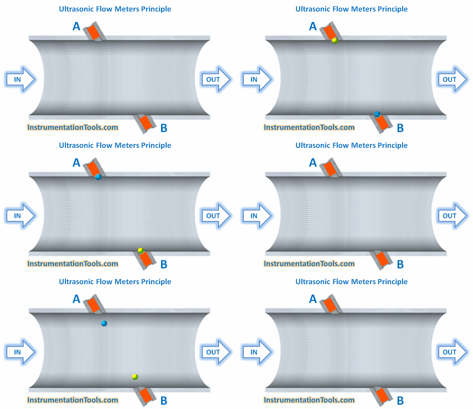
Ultrasonic Flow Meters Working Principle

Ultrasonic Flow Meters Working Principle

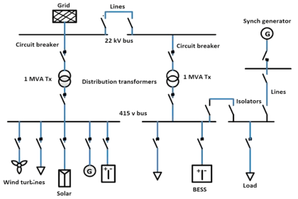
Single Line Diagram (SLD) Example

Electrical Drawings

Burst Transformers Root Cause Analysis

Root Cause Analysis – Burst Transformers and 11 kV Input Breakers

Humming Sound in Transformer

Why is the Humming Sound Produced in Transformer?

Differences between Watts and Volt Amps

Differences between Watts and Volt Amps

Learn More

Converter Instruction in Siemens PLC Programming

Converter Instruction in Siemens PLC Programming

Zero Suppression in level Measurement

Zero Suppression and Zero Elevation Calculations

Emergency Shutdown System

What is Emergency Shutdown System (ESD) ?

COCO Simulator

COCO Simulator: Free Process Simulation Software

Turbine Control System

Turbine Control System

PLC FBD Programming for Burglar Alarm Security System

PLC FBD Programming for Burglar Alarm Security System

non-contact pyrometer principle

Non-contact Temperature Sensors

Top 100 LabVIEW Projects for Engineering Students

Top 100 LabVIEW Projects for Engineering Students

Menu

  • About
  • Privacy Policy
  • Copyright

Quick Links

  • Learn PLC
  • Helping Hand
  • Part Time Job

YouTube Subscribe

Follow US
All rights reserved. Reproduction in whole or in part without written permission is prohibited.
Welcome Back!

Sign in to your account

Username or Email Address
Password

Lost your password?