The method of representing, encoding, and transmitting the data is called the protocol.
At the field level, the dominant protocols for process instruments are HART, FOUNDATION Fieldbus H1 and PROFIBUS PA.
Fieldbus, Profibus and HART Protocols
Foundation Fieldbus is an all-digital, serial, two-way communications system that serves as the base-level network in a plant or factory automation environment.
The FOUNDATION Fieldbus specification is uniquely different from other networking technologies. Foundation Fieldbus is not only a communications protocol but also a programming language for building control strategies.
In FF, one of the possibilities that a standard programming language and powerful communications features enable is the ability to perform control that is distributed into the field devices rather than a central controller
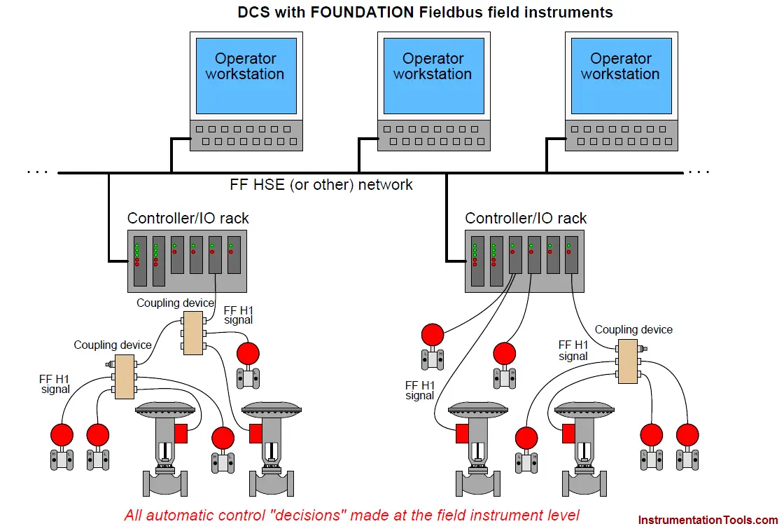
For example, it is common for the Fieldbus valve positioner to act as a controller for the loop as it is part of. PID controller can implement in DCS system ( also called as Host or Remote systems). In fieldbus devices, PID controller function can also implement in fieldbus device configurations (also called as local system). So, for fieldbus devices we can implement the PID function either in DCS system or in fieldbus device or at both places.
In fieldbus, It executes the PID function block but only for its own loop, not for other loops. This new architecture based on field device capability is called Field Control System (FCS) and is an alternative to DCS.

Foundation Fieldbus was originally intended as a replacement for the 4-20 mA standard, and today it coexists alongside other technologies such as Modbus, Profibus, and Industrial Ethernet.
A typical fieldbus segment consists of the following components.
- H1 card – fieldbus interface card (It is common practice to have redundant H1 cards, but ultimately this is application specific)
- PS – Bulk power (Vdc) to Fieldbus Power Supply
- FPS – Fieldbus Power Supply and Signal Conditioner (Integrated power supplies and conditioners have become the standard nowadays)
- T – Terminators (Exactly 2 terminators are used per fieldbus segment. One at the FPS and one at the furthest point of a segment at the device coupler)
- LD – Linking Device, alternatively used with HSE networks to terminate 4-8 H1 segments acting as a gateway to an HSE backbone network.
- And fieldbus devices, (e.g. transmitters, transducers, etc.)
The HART protocol does allow several devices to be multi-dropped on a single pair of wires, but this is a capability infrequently explored because of the low update speed, typically half a second per device.
For a vast majority of installations HART devices are connected point to point, that is, one pair of wires for each device and a handheld connected temporarily from time to time for configuration and maintenance.
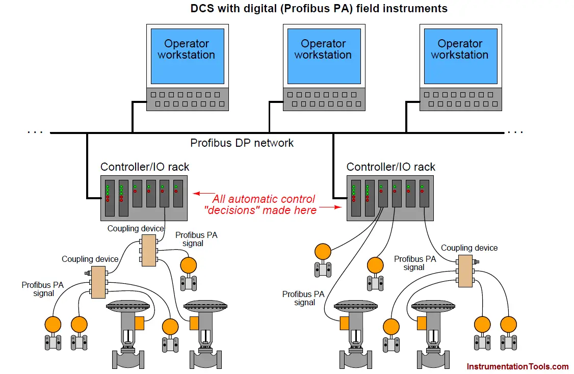
Both FOUNDATION Fieldbus H1 and PROFIBUS PA are completely digital and even use identical wiring, following the IEC 61158-2 standard.
Communications Subsystem Differences
The communications interfaces required by a host are different for the pure digital communication in FOUNDATION Fieldbus and PROFIBUS on the one hand and for the hybrid of analog and digital for HART on the other.
For PROFIBUS and FOUNDATION Fieldbus a single integrated network architecture is used for I/O as well as for asset management.
The HART and PROFIBUS technologies do not have a control strategy programming language. FOUNDATION Fieldbus has a standard function block language and publisher/subscriber communication.
FOUNDATION Fieldbus has a number of useful communication features not offered by HART protocol. These include automatic device detection and address assignment for Plug-and-Play installation and time synchronization.
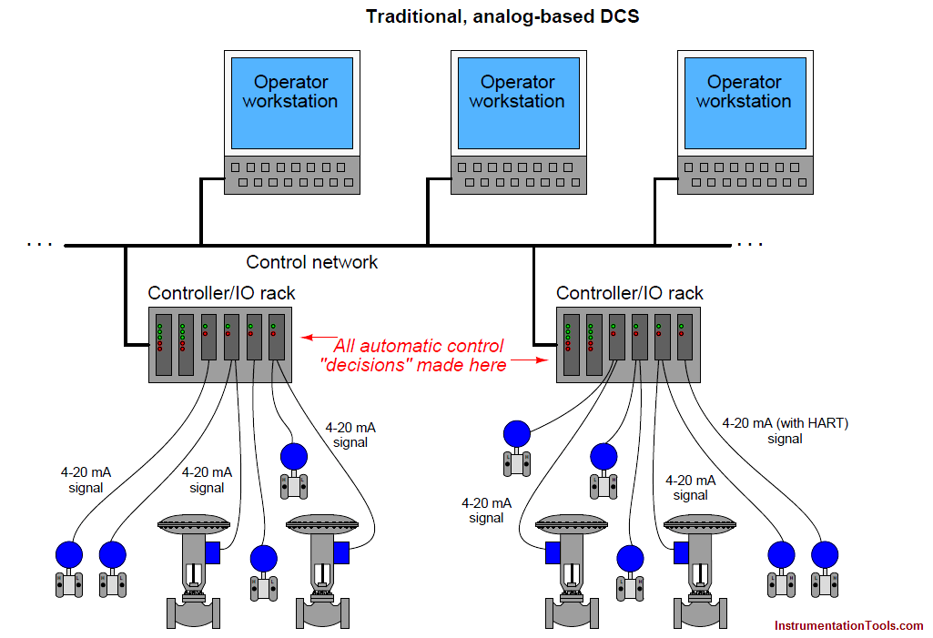
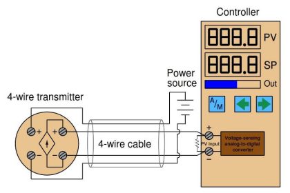
As HART communication speed is low it relies on the analog 4-20 mA signal for real-time process I/O and a HART device is therefore connected point to point.
In most systems, the 4-20 mA only connects to conventional I/O modules via individual wires, and any communication with the device is performed with a temporarily connected portable hand communicator. Field devices, and host, are integral parts of the system.
PROFIBUS has PROFIsafe for communication between instruments in safety- related systems, which FOUNDATION and HART do not offer
Basic Network Differences
It is technically possible to use FOUNDATION Fieldbus or PROFIBUS PA technology in any kind of system architecture. Systems based on conventional architecture can also benefit from the wire reduction made possible by field-level networks.
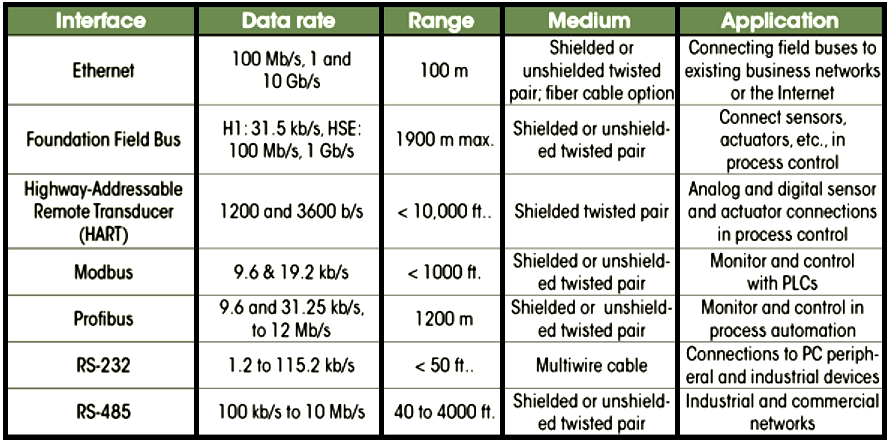
Compare Fieldbus Protocols
Summary
- Fieldbus systems are complex, more training is needed, HART systems are easily understandable.
- Field bus test devices are more complex.
- Price of field bus devices are higher than HART enabled.
Read Next:
- Fieldbus vs 4-20mA
- What is HART Protocol ?
- Foundation Fieldbus Logics
- 7 OSI Layers of Communication
- What is HART- IP ?


Very good
I believe I learned a lot from this publication thanks
i have learn from the publication.
This quite inspiring I have learnt a lot I need to purse Automation how best can I do it
Thank you
Regards
Gondai Mlambo
I didn’t miss any articles that were published on this site. Briefing excellently maximum time. Thanks.
Md. Rajon mahmud, Bangladesh.
this article is very helpful to me
Thanks a lot
I really interested for the instrumentation and control processes and procedures on how to calibrate a device and control:thanks