Inst ToolsInst ToolsInst Tools
  • Courses
  • Automation
    • PLC
    • Control System
    • Safety System
    • Communication
    • Fire & Gas System
  • Instrumentation
    • Design
    • Pressure
    • Temperature
    • Flow
    • Level
    • Vibration
    • Analyzer
    • Control Valve
    • Switch
    • Calibration
    • Erection & Commissioning
  • Interview
    • Instrumentation
    • Electrical
    • Electronics
    • Practical
  • Q&A
    • Instrumentation
    • Control System
    • Electrical
    • Electronics
    • Analog Electronics
    • Digital Electronics
    • Power Electronics
    • Microprocessor
  • Request
Search
  • Books
  • Software
  • Projects
  • Process
  • Tools
  • Basics
  • Formula
  • Power Plant
  • Root Cause Analysis
  • Electrical Basics
  • Animation
  • Standards
  • 4-20 mA Course
  • Siemens PLC Course
Reading: Ferrules and Cross Ferruling
Share
Font ResizerAa
Inst ToolsInst Tools
Font ResizerAa
  • Courses
  • Design
  • PLC
  • Interview
  • Control System
Search
  • Courses
  • Automation
    • PLC
    • Control System
    • Safety System
    • Communication
    • Fire & Gas System
  • Instrumentation
    • Design
    • Pressure
    • Temperature
    • Flow
    • Level
    • Vibration
    • Analyzer
    • Control Valve
    • Switch
    • Calibration
    • Erection & Commissioning
  • Interview
    • Instrumentation
    • Electrical
    • Electronics
    • Practical
  • Q&A
    • Instrumentation
    • Control System
    • Electrical
    • Electronics
    • Analog Electronics
    • Digital Electronics
    • Power Electronics
    • Microprocessor
  • Request
Follow US
All rights reserved. Reproduction in whole or in part without written permission is prohibited.
Inst Tools > Blog > Instrumentation Design > Ferrules and Cross Ferruling

Ferrules and Cross Ferruling

Ferrules are identification labels provided for every wire terminations in an instrument, equipment, and control panels.

Last updated: March 6, 2021 6:10 pm
Editorial Staff
Instrumentation Design PLC Tutorials
No Comments
Share
2 Min Read
SHARE

Ferrules are identification labels provided for every wire terminations in an instrument, equipment, or electrical/instrumentation control panels.

Contents
Typical FerruleCross FerrulingCross Ferrule TagFerrule Example

These tube-shaped sleeves can be inserted easily on each individual wire in a multi-core cable.

In earlier days fixed digits/letters are used as ferrules, but now Instrumentation engineers/technicians prints out desired ferrules by using a ferrule printing machine.

Typical Ferrule

Typical Ferrule

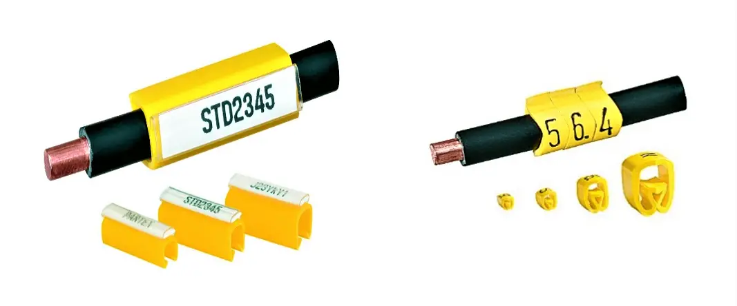
The numbers/ letters on the ferrules will be given as per the approved electrical hook up or loop diagrams.

This helps technicians to easily identify a particular loop/wiring from a series of terminal blocks and to troubleshoot the desired terminal connection.

Separate numbers on the ferrules distinguish the positive and negative polarities of wires, thus ensure the polarity protection of the instrument.

Cross Ferruling

 As a wire is connected on its both ends, it is quite useful to use a cross reference method for wire identification.

Unlike normal ferruling methods, cross ferruling gives information about the wire source as well as the destination, details about the Installation area, Panel, Junction Box, Terminal, and Polarity.

Cross Ferrule Tag

Structure of a typical Cross ferrule tag is shown below.

Cross Ferruling

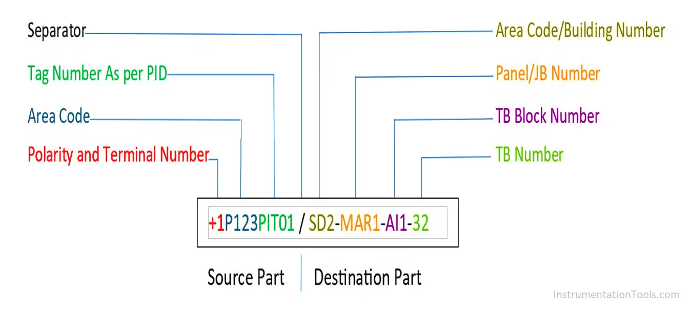
With all this information on a cross ferrule, technical personal get a clear idea of the loop wiring and are able to do the job very efficiently.

Ferrules

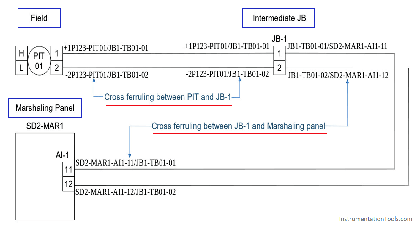
The above figure shows a typical loop diagram for a two-wire transmitter.

An intermediate JB is provided in between the control and field sides.

Each wire is provided with cross ferrules on both ends.

As shown in the above figure, Cross ferruling is used in between field – JB, and JB – Marshaling panels.

Each ferrule at the terminations gives a clear idea of where the other end is connected.

Ferrule Example

Ferrule Example
Ferrule Example

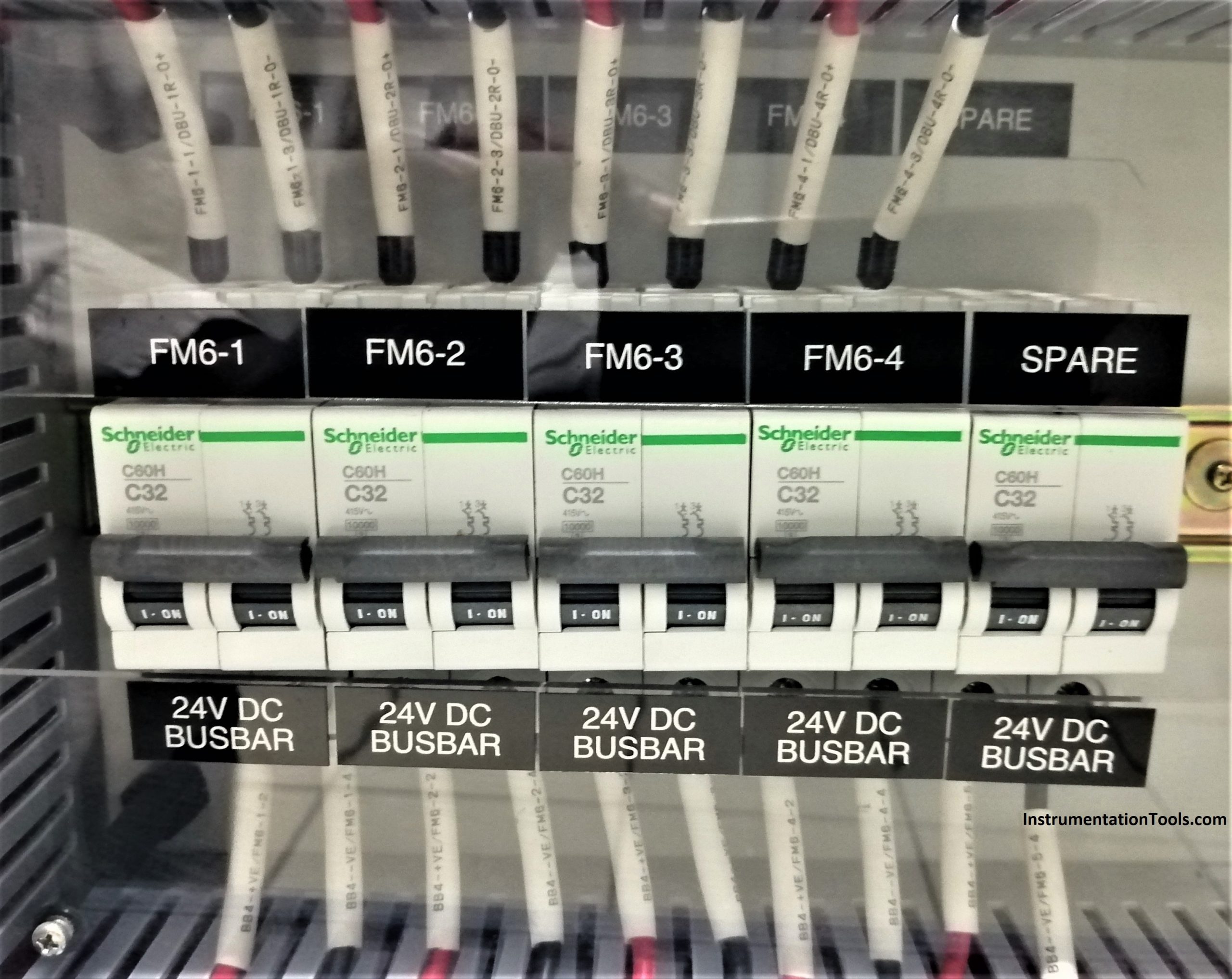
In the above image, all wires connected to the MCB’s are provided with labelling. It will help us to locate the respective inputs and outputs and helps us to trace the wires and troubleshooting will be easier.

Author: Visal KA

Don't Miss Our Updates
Be the first to get exclusive content straight to your email.
We promise not to spam you. You can unsubscribe at any time.
Invalid email address
You've successfully subscribed !

Continue Reading

Instrumentation Deliverables Generated from 3D Modeling
Free Allen Bradley PLC Ladder Logic Training Course
Package System Architecture – Control & Instrumentation
#9 PLC Best Practices – Validate indirections
Top 100 PLC Objective Questions and Answers
SCADA Systems
Share This Article
Facebook Whatsapp Whatsapp LinkedIn Copy Link
Share
Leave a Comment

Leave a Reply Cancel reply

Your email address will not be published. Required fields are marked *

Stay Connected

128.3kFollowersLike
69.1kFollowersFollow
210kSubscribersSubscribe
38kFollowersFollow

Categories

Explore More

Conveyor Sorting System with Color Detection PLC Logic
How to Convert Current to Voltage using Resistor ?
General Specification of Thermowell
Safety Door Interlock PLC Program
Switch or Transmitter
Motion Detection based Street Light: PLC Logic Solution
Value Assignments in SCL Language – Single, Multiple, Combined
PLC Functional Block Diagram for Logic Gates

Keep Learning

PLC Program for Conditional Control Logic

PLC Program for Conditional Control Logic

PLC Subroutine

Allen Bradley PLC Subroutines

PLC Problems Troubleshooting

PLC Problems Troubleshooting

Brands PLC communication interface and protocol

Communicating Between Siemens PLC and Other PLC Brands

How to Upload PLC Program in Siemens PLC if Upload Icon is Disabled

Upload Option Disabled in Siemens PLC

PLC Ladder Program for Automatic Car Wash

PLC Ladder Program for Automatic Car Wash using Siemens TIA Portal

Distributed IO for Siemens PLC

How to Configure Distributed IO in a PLC Project?

Your First Steps Through STL Language

Your First Steps Through STL Language

Learn More

Top 100 PLC Objective Questions and Answers

Top 100 PLC Objective Questions and Answers

Concept of Interlocking in PLC

Concept of Interlocking in PLC

hipps

What is High Integrity Pressure Protection System?

Configure Analog Inputs and Outputs in Delta PLC

How to Configure Analog Inputs and Outputs in Delta PLC?

Stability in Frequency Domain

Nyquist Stability Criterion

PLC Programmer Salary and Future Career Scope

PLC Programmer Salary and Future Career Scope

peak of a chromatogram

Measuring Gases Concentration in Chromatograph

Facts of Control Valves

Facts About Control Valves

Menu

  • About
  • Privacy Policy
  • Copyright

Quick Links

  • Learn PLC
  • Helping Hand
  • Part Time Job

YouTube Subscribe

Follow US
All rights reserved. Reproduction in whole or in part without written permission is prohibited.
Welcome Back!

Sign in to your account

Username or Email Address
Password

Lost your password?