Inst ToolsInst ToolsInst Tools
  • Courses
  • Automation
    • PLC
    • Control System
    • Safety System
    • Communication
    • Fire & Gas System
  • Instrumentation
    • Design
    • Pressure
    • Temperature
    • Flow
    • Level
    • Vibration
    • Analyzer
    • Control Valve
    • Switch
    • Calibration
    • Standards
    • Basics
    • Formula
    • Erection & Commissioning
    • Process Fundamentals
    • Root Cause Analysis
  • Interview
    • Instrumentation
    • Electrical
    • Electronics
    • Practical
  • Q&A
    • Instrumentation
    • Control System
    • Electrical
    • Electronics
    • Analog Electronics
    • Digital Electronics
    • Power Electronics
    • Microprocessor
Search
  • Courses
  • PLC
  • Control Systems
All rights reserved. Reproduction in whole or in part without written permission is prohibited.
Reading: Communication between Factory IO and Siemens Tia Portal
Share
Notification Show More
Font ResizerAa
Inst ToolsInst Tools
Font ResizerAa
  • Courses
  • PLC
  • Control Systems
Search
  • Courses
  • Automation
    • PLC
    • Control System
    • Safety System
    • Communication
    • Fire & Gas System
  • Instrumentation
    • Design
    • Pressure
    • Temperature
    • Flow
    • Level
    • Vibration
    • Analyzer
    • Control Valve
    • Switch
    • Calibration
    • Standards
    • Basics
    • Formula
    • Erection & Commissioning
    • Process Fundamentals
    • Root Cause Analysis
  • Interview
    • Instrumentation
    • Electrical
    • Electronics
    • Practical
  • Q&A
    • Instrumentation
    • Control System
    • Electrical
    • Electronics
    • Analog Electronics
    • Digital Electronics
    • Power Electronics
    • Microprocessor
Follow US
All rights reserved. Reproduction in whole or in part without written permission is prohibited.
Inst Tools > Blog > PLC Tutorials > Communication between Factory IO and Siemens Tia Portal

Communication between Factory IO and Siemens Tia Portal

Last updated: March 4, 2021 12:06 pm
Editorial Staff
PLC Tutorials
1 Comment
Share
4 Min Read
SHARE

This article is about communication between Siemens TIA PORTAL and Factory IO. You can use actual PLC to check your logic. You can also create an animation as per your actual layout and test the logic.

Here, I don’t have actual PLC so, I will use Siemens simulator to test the logic.

Factory IO and Siemens Tia Portal

I will explain communication with a simple example that contains START, STOP switches as inputs, and conveyor as OUTPUT which is to be controlled from inputs. I will also light the lamp to indicate the START and STOP status of the conveyor, lamps are OUTPUTs here.

So, I will use two INPUTs and three OUTPUTs in my example. Let’s begin with communication.

Step 1:

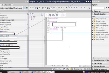
First, open the TIA portal. Enter into the Programming environment.

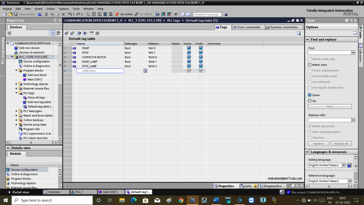
First, I will create a symbol table to define Input and Output tags as shown in the below window.

Communication with Factory IO

Step 2:

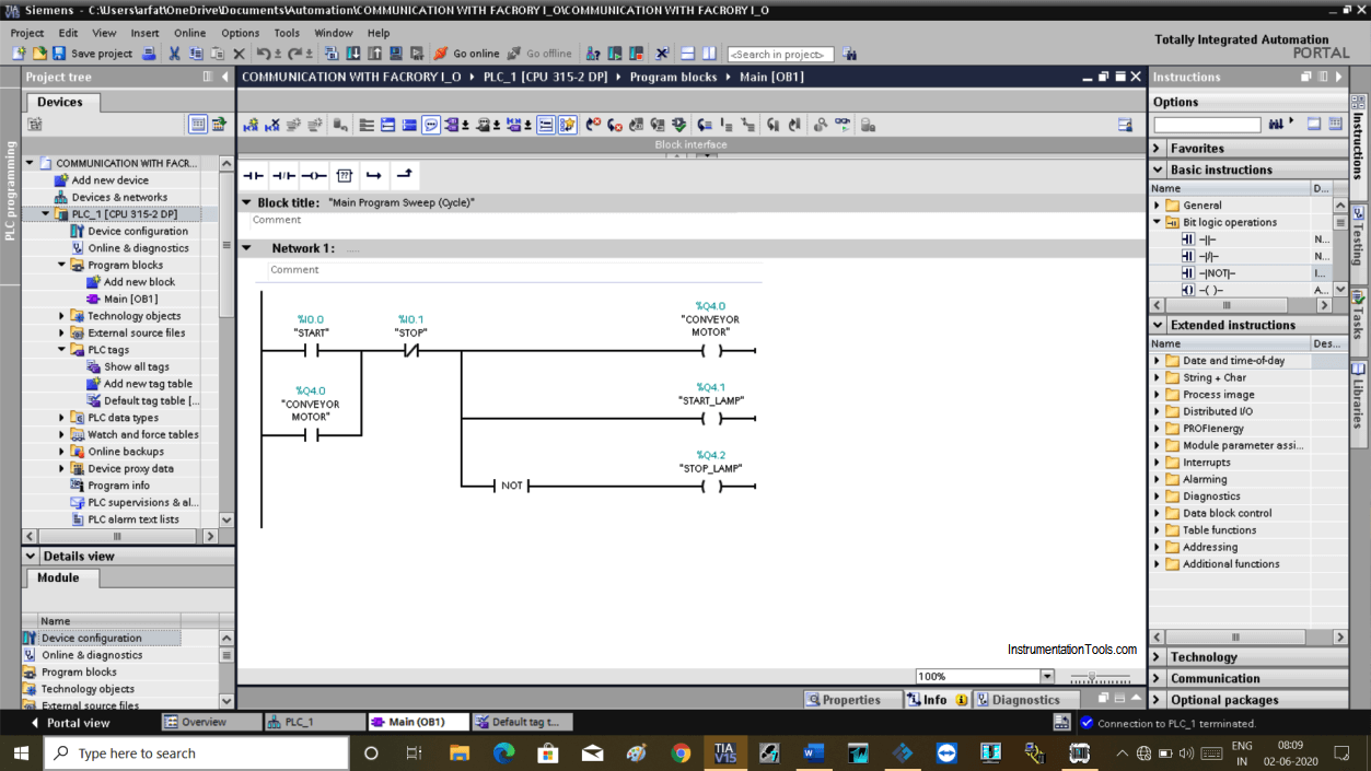
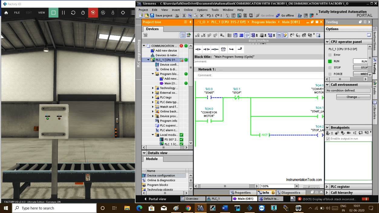
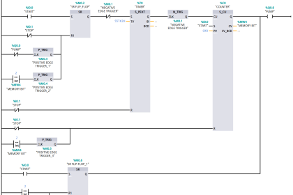
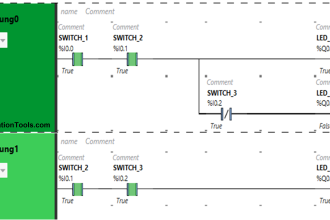
Now write the PLC program shown below to turn ON the conveyor motor.

PLC program to turn on the conveyor

Step 3:

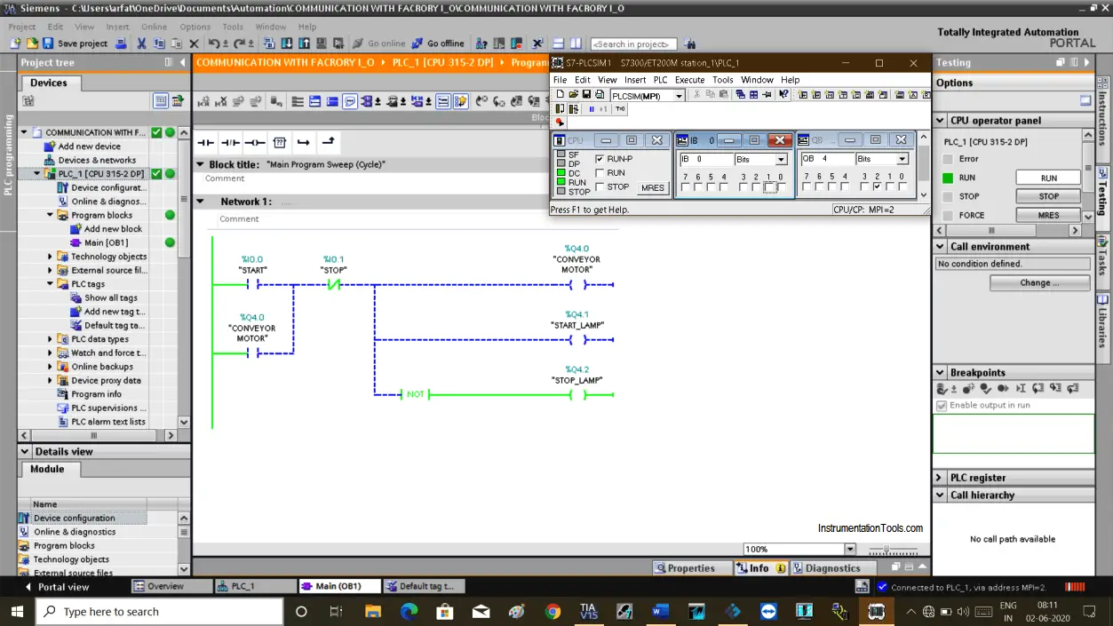
Now, load this program in a simulator and put it in to run mode.

PLC Program in Run Mode

Step 4:

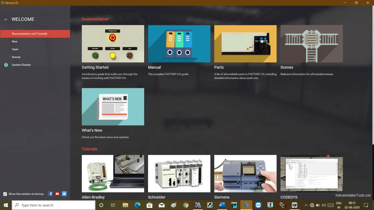
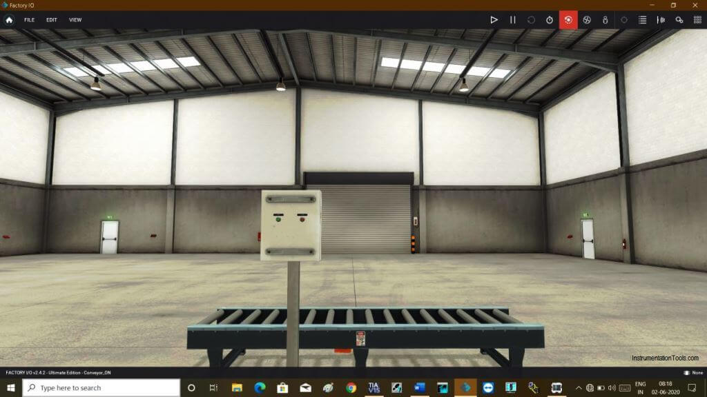
Now, open Factory I/O software.

You can create a new scene or can use a scene that is already created in the factory I/O.

Factory IO

Step 5:

Here, as I want to turn ON conveyor, I have to create a new scene as shown in the below figure.

As I aim to show you communication my animation is too simple.

I have added START, STOP pushbutton, and conveyor as per Input and Output, which are used in my PLC programming.
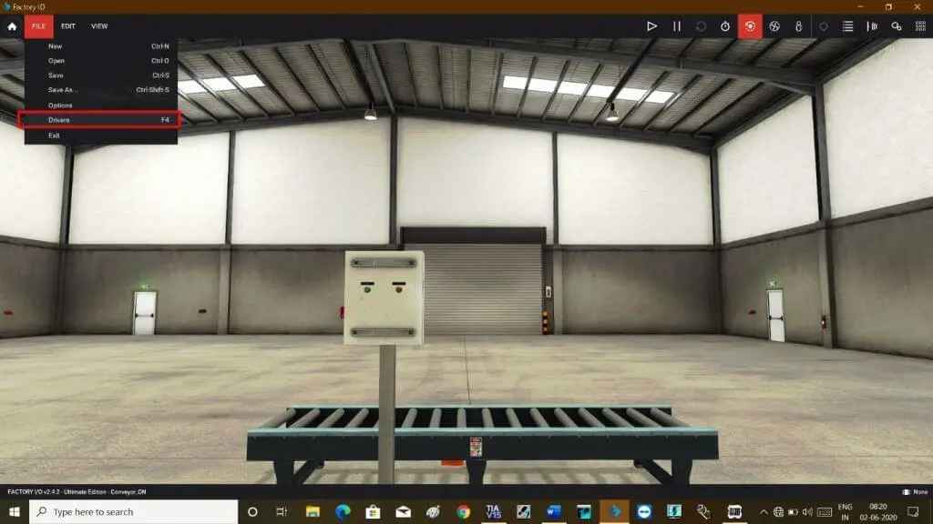
Factory IO PLC programming

Step 6:

Now, Go to the file menu and select the driver to configure the simulator.
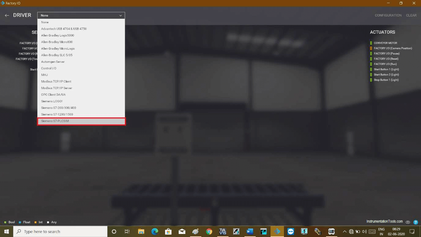
configure the simulator

Step 7:

Open the drop-down menu and select “Siemens S7 PLCSIM”. Click on it to add the I/O module.
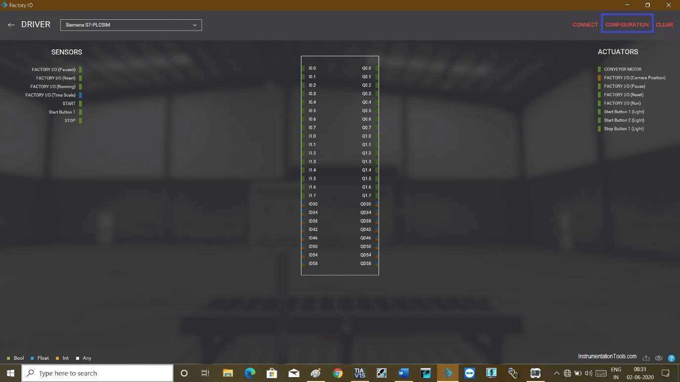
Siemens S7-PLCSIM

Step 8:

The following module will be added. Now, click on “configuration” to configure module which we have used in our PLC program.
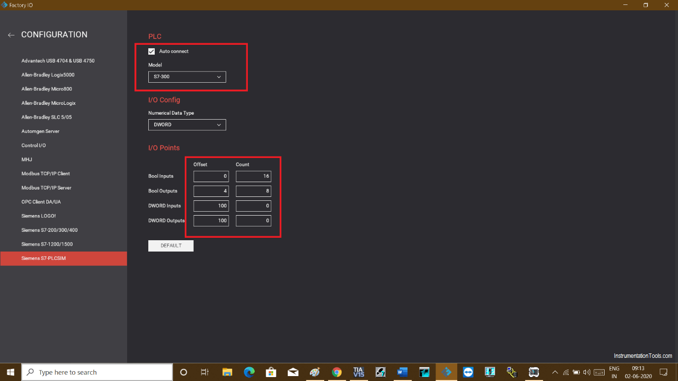
Configuration of Factory IO Software

Step 9:

In the configuration window, select the checkmark to automatically connect PLC.

In “I/O points” choose the starting address of your PLC Input and output. “Offset” represent the starting address which is in our case start from “0 (zero)” for Input and “4” for Output.

“Count” represents the number of Inputs and outputs available in the PLC module.

Automatically connect PLC

Step 10:

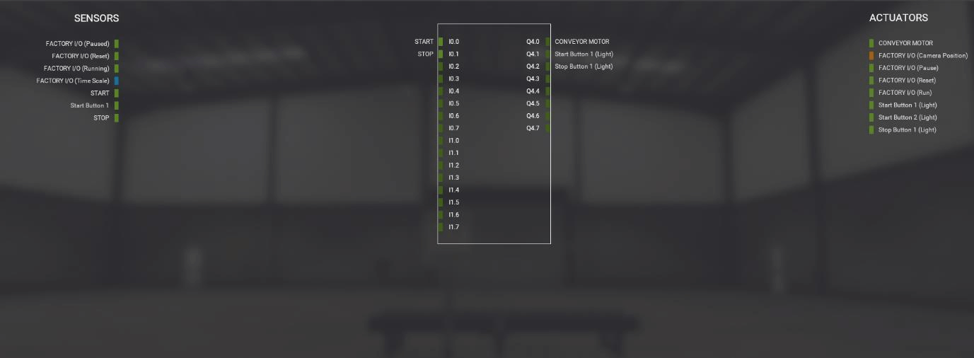
After configuration, go back to the driver window. Now drag and drop Inputs and Outputs which we have used in our programming.

Simply drag Inputs or outputs from the Sensor and Actuator tab and put them into the module as shown in the below window.
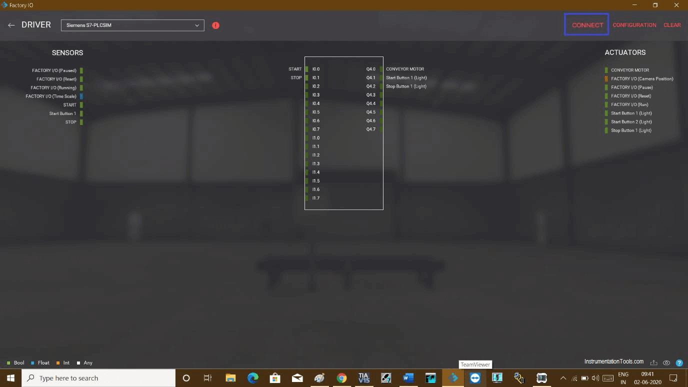
Factory IO Sensor and Actuator

Step 11:

Click on the “connect” icon to connect it with the simulator.
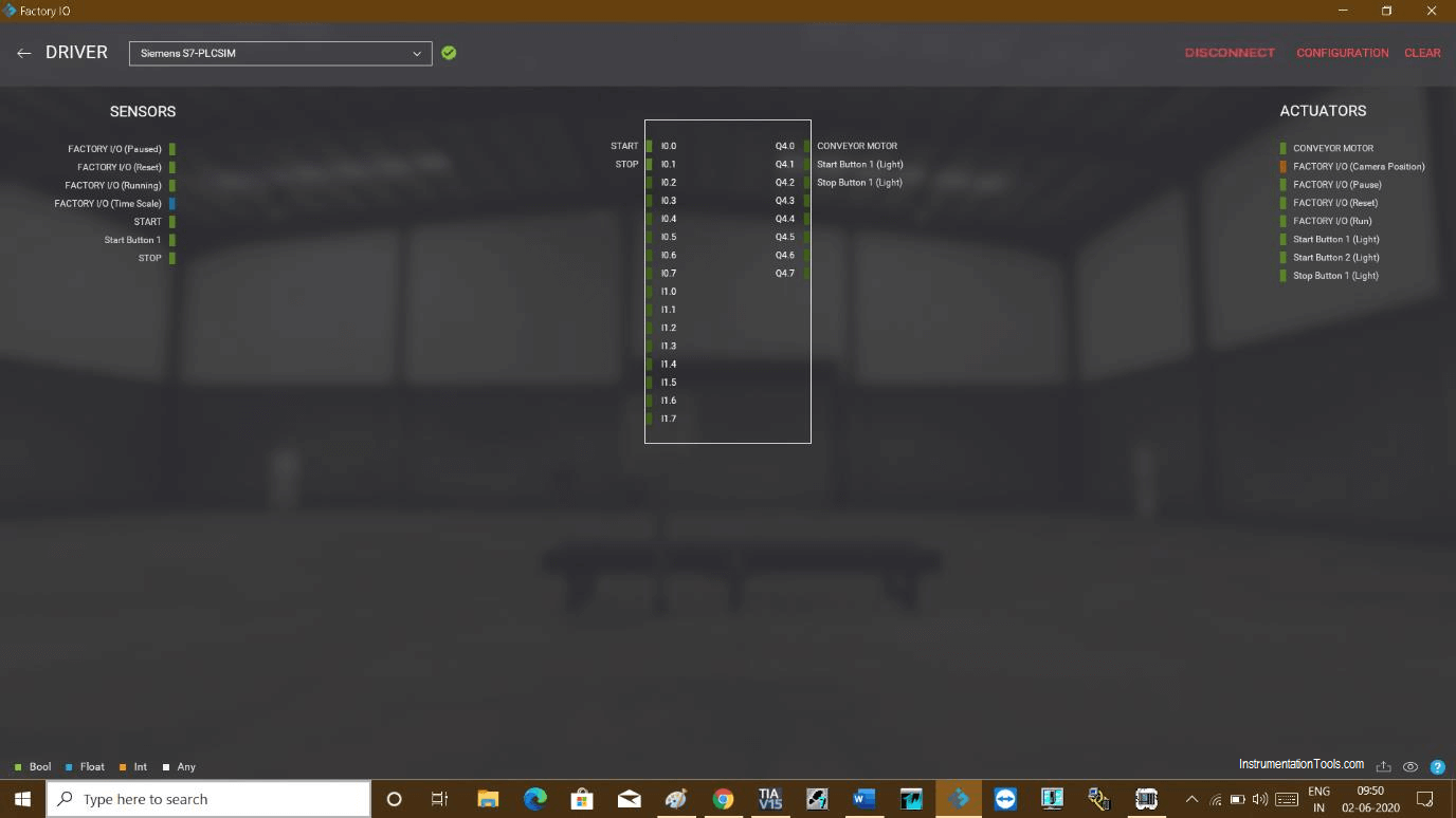
Connect Factory IO with Simulator

Step 12:

On successful communication, the right checkmark will appear next to the driver option.

Factory IO communication

Step 13:

Now test the logic. As I have used pushbutton, if I press it and release it, due to latching in the program, it won’t stop, light and motor both will energize continuously.
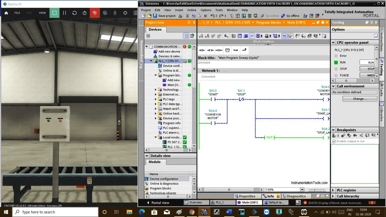
Test the logic in Factory IO

Step 14:

As soon as I press the stop button, it stops the motor and the stop lamp will turn ON.

Communication between Factory IO and Siemens Tia Portal

Author: Suhel Patel

If you liked this article, then please subscribe to our YouTube Channel for PLC and SCADA video tutorials.

You can also follow us on Facebook and Twitter to receive daily updates.

Read Next:

  • Extended Timer Logic in PLC
  • Pulse Generation Timer
  • Allen Bradley RSLogix
  • FIFO Instruction in PLC
  • Motor Ladder Logic in PLC
Don't Miss Our Updates
Be the first to get exclusive content straight to your email.
We promise not to spam you. You can unsubscribe at any time.
Invalid email address
You've successfully subscribed !

Continue Reading

PLC Digital Input and Digital Output Modules
Forcing and Modifying PLC Logic
Difference Between PLC and CNC Machine
How to Wire a Field instrument to Control Room with Example
Door Lock with Delay PLC Exercise Problems
PLC Program for Washing Machine
Share This Article
Facebook Whatsapp Whatsapp LinkedIn Copy Link
Share
1 Comment
  • Moshi says:
    September 22, 2023 at 11:03 am

    I tried to connect it says
    “It seems that S7-PLCSIM V13/V14 is not running. Please start it and try again.”

    Reply

Leave a Reply Cancel reply

Your email address will not be published. Required fields are marked *

Stay Connected

128.3kFollowersLike
69.1kFollowersFollow
208kSubscribersSubscribe
38kFollowersFollow

Categories

Explore More

Contacts and Coils in PLC Ladder Logic
Best Practices of PLC Wiring – Programmable Logic Controller
System Cabinet Health Checks – PLC and DCS Industrial Automation
Value Assignments in SCL Language – Single, Multiple, Combined
PLC Compressor Control Ladder Logic
Siemens PLC programming: BCD, Integer, Double Integer, Real
PLC Conveyor Ladder Logic Program
Timer in Studio 5000 – TON, TOF, RTO

Keep Learning

PLC Examples for calling functions in SCL

How to Insert Block Calls in SCL Language?

Ladder Logic Counters Instruction

Up Counter PLC Program

Allen-Bradley SLC 500

History of Programmable Logic Controllers (PLC)

Simulation in Machine Expert HVAC

How to do Simulation in Schneider PLC?

Level Transmitter configuration in PLC

Scaling with Parameters (SCP) Instruction in PLC

Draw a Ladder Logic to control a bulb using push buttons in PLC

Concept of Latching in PLC

Does Really a Safety Barrier is Important

Does Really a Safety Barrier is Important? – PLC DCS Systems

Timer STL Programming

Timers using Statement List (STL) PLC Programming

Learn More

Leaky Boiler Drum Level Switch

Leaky Boiler Drum Level Switch Stops NH3 Plant Commissioning

LES and GRT Blocks in PLC Programming

Allen Bradley Math Functions

Analyzers Questions and Answers

Biosensors Questions & Answers

Electrician Tools

Electrician Tools MCQ Questions

Liapunov’s Stability Analysis

Liapunov’s Stability Criterion – Part II

Multiple Pumps Control using PLC

Multiple Pumps Control using PLC

Power Electronics Objective Questions

Cycloconverters Objective Questions

SIS Verification & Validation - Safety Instrumented System

SIS Verification & Validation – Safety Instrumented System

Follow US
All rights reserved. Reproduction in whole or in part without written permission is prohibited.
Welcome Back!

Sign in to your account

Username or Email Address
Password

Lost your password?