In general, to make a flip-flop lamp application, you can use transistors with the help of capacitors as a timer for ‘ON’ and ‘OFF’ actions.
However, in devices that operate using a certain program, the Flip-Flop lamp application can be easily made just by utilizing the timer function as a timer.
If the microcontroller is used to make flip-flop light applications, it only utilizes the time lag or delay condition to turn ON and OFF of a lamp. In PLC we can take advantage of the Timer function and use ladder diagram language for the same application.
Example of Flip-Flop PLC Program
This Flip-Flop PLC program uses 3 Digital Input contacts (PB_START, PB_STOP, RESET), 2 Digital Output contacts (LAMP_1, LAMP_2), 2 Timers (TIMER_0, TIMER_1), 4 Bit Memory allocation contacts (IR_MASTER, IR_TIMER_0,IR_TIMER_1, IR_COUNTER), 4 Word Memory allocation areas (PV_COUNTER, SV_COUNTER, SV_TIMER_0, SV_TIMER_1).
When the PB_START (%I0.0) button is activated then the system will be started and will turn ON the Coil IR_MASTER (%M0), at the same time it will also activate TIMER_0 (%TM0) and Digital Output LAMP_1 (%Q0.0).
When TIMER_0 (%TM0) has reached its Preset value, it activates TIMER_1 (%TM1). The active Digital Output changes to LAMP_2 (%Q0.1) for a long time until TIMER_1 (%TM1) reaches its Preset value, while the Digital Output LAMP_1 (%Q0.0) turns OFF.
Digital Output LAMP_1 (%Q0.0) and LAMP_2 (%Q0.1) will light alternately several times according to the preset counter value that has been set. The actual value (PV_Counter) can be RESET and the Preset value (SV_COUNTER) can be varied.
Preset values of TIMER_0 (%TM0) and TIMER_1 (%TM1) can be set respectively. The system can only stop if PB_STOP(I0.1) and IR_COUNTER(%M3) are enabled.
I/O Addressing
The Input, Output, TIM, Bit Memory, and Word Memory addresses are shown below.
| Comment | Input (I) | Output (Q) | Bit Memory | Word Memory | TIMERS |
| PB_START | %I0.0 | ||||
| PB_STOP | %I0.1 | ||||
| RESET | %I0.2 | ||||
| LAMP_1 | %Q0.0 | ||||
| LAMP_2 | %Q0.1 | ||||
| TIMER_0 | %TM0 | ||||
| TIMER_1 | %TM1 | ||||
| IR_MASTER | %M0 | ||||
| IR_TIMER_0 | %M1 | ||||
| IR_TIMER_1 | %M2 | ||||
| IR_COUNTER | %M3 | ||||
| PV_COUNTER | %MW0 | ||||
| SV_COUNTER | %MW1 | ||||
| SV_TIMER_0 | %MW2 | ||||
| SV_TIMER_1 | %MW3 |
Programming of PLC Code
Initial Setup
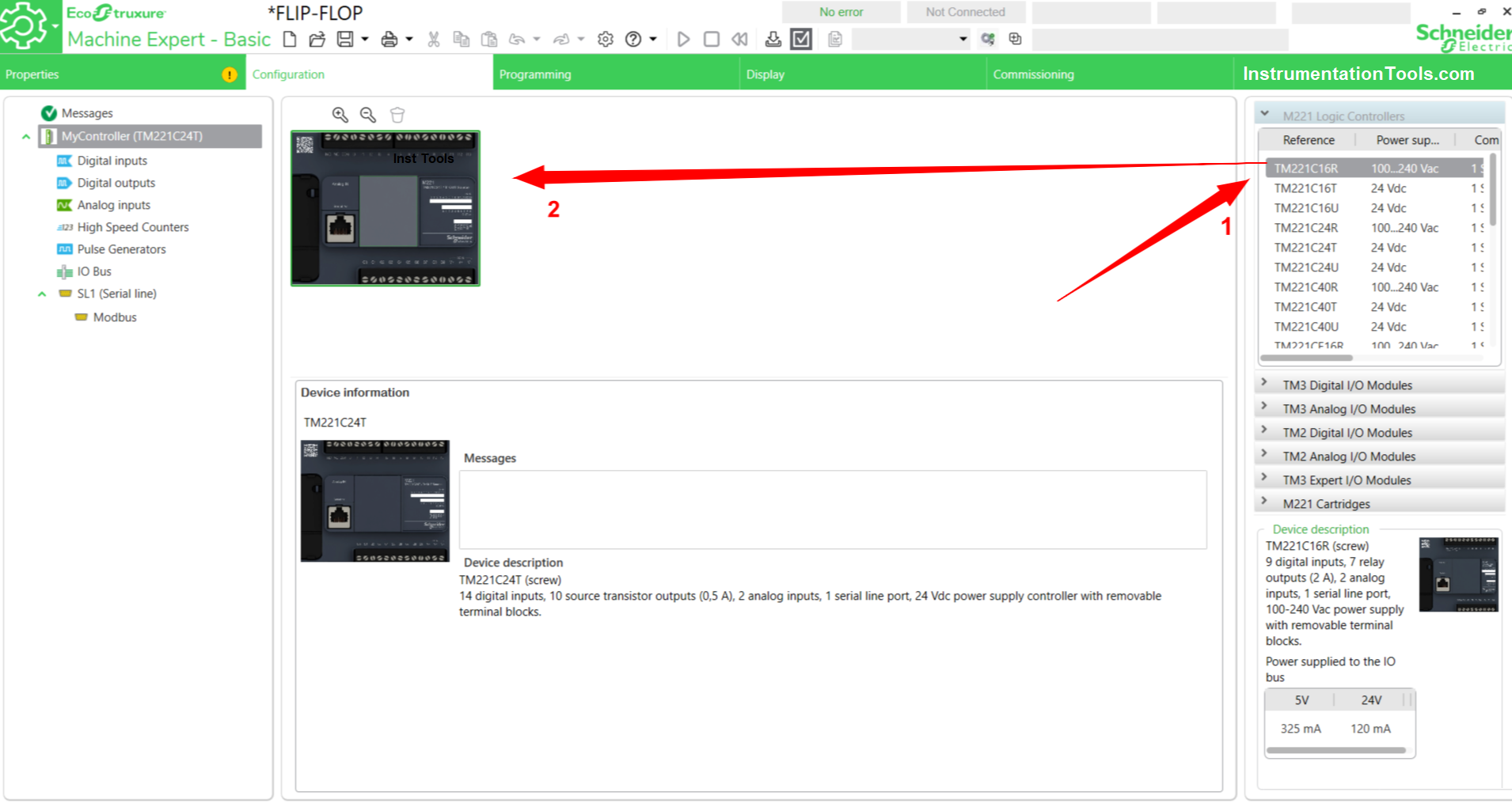
Open Ecostruxure Machine-Basic Software, and enter the Configuration menu to set the type of PLC used, and Digital Input / Output contact settings to be used.
Choose PLC type PLC as needed, in this program, I use type TM221C24T. To change or add PLC we can click the type of PLC in the list column and then drag it to the work page as shown below.
Set Up Digital Input Contacts
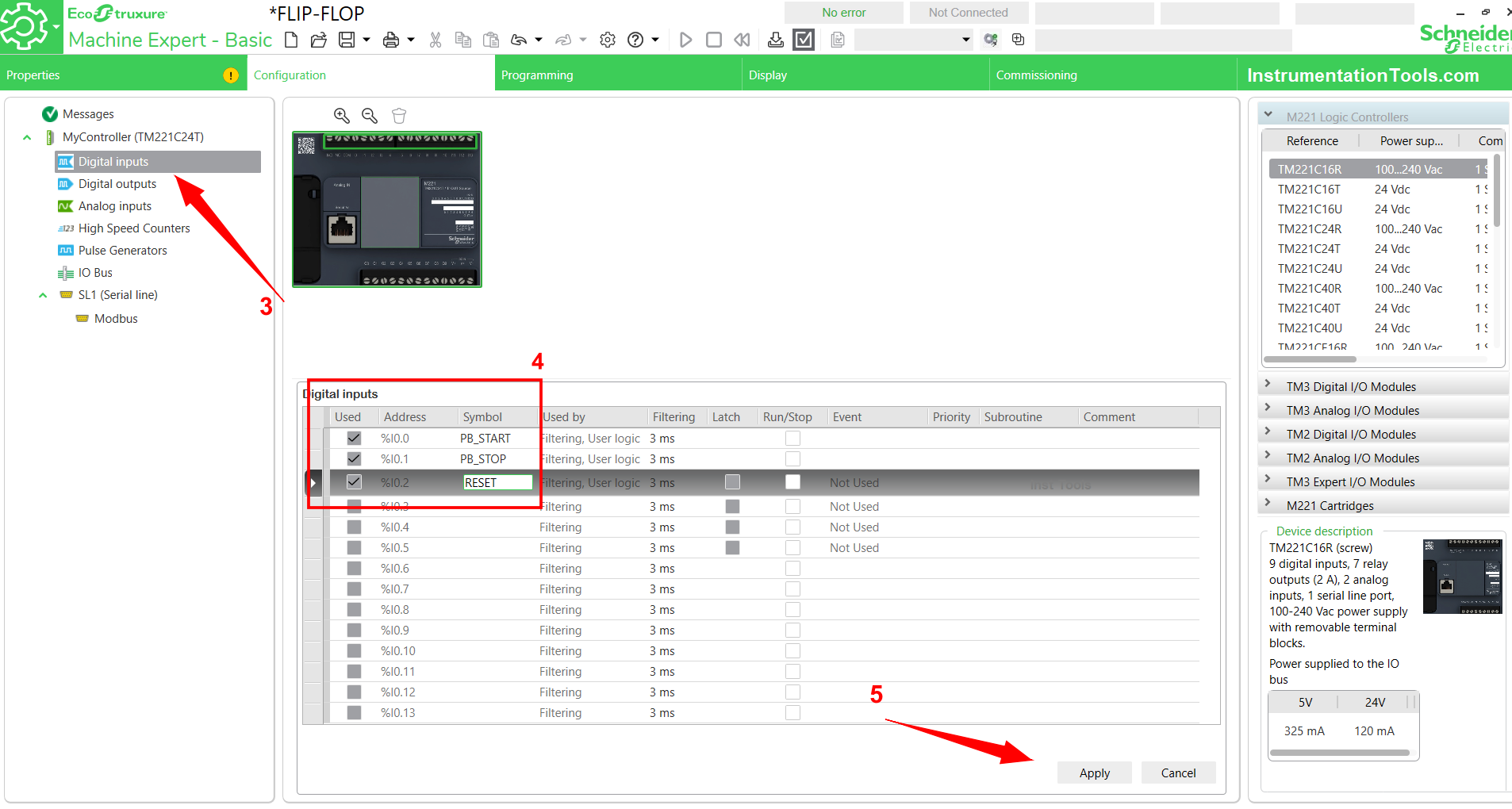
To set the Digital Input contact parameters, we have to press the Digital Input sub-menu first, then a list of Digital Input contact address parameters will appear on the work page as shown below.
Select the number of contacts to use, then name the SYMBOL column (as shown in box no.4). This program uses 3 Digital Inputs with names/labels PB_START, PB_STOP, and RESET.
When finished, click the “Apply” button to apply the settings that have been done. In Ecostruxure Machine-Basic Software, the Digital Input address uses the format %I0.0 – %I0.xxx.
Set Up Digital Contact Output
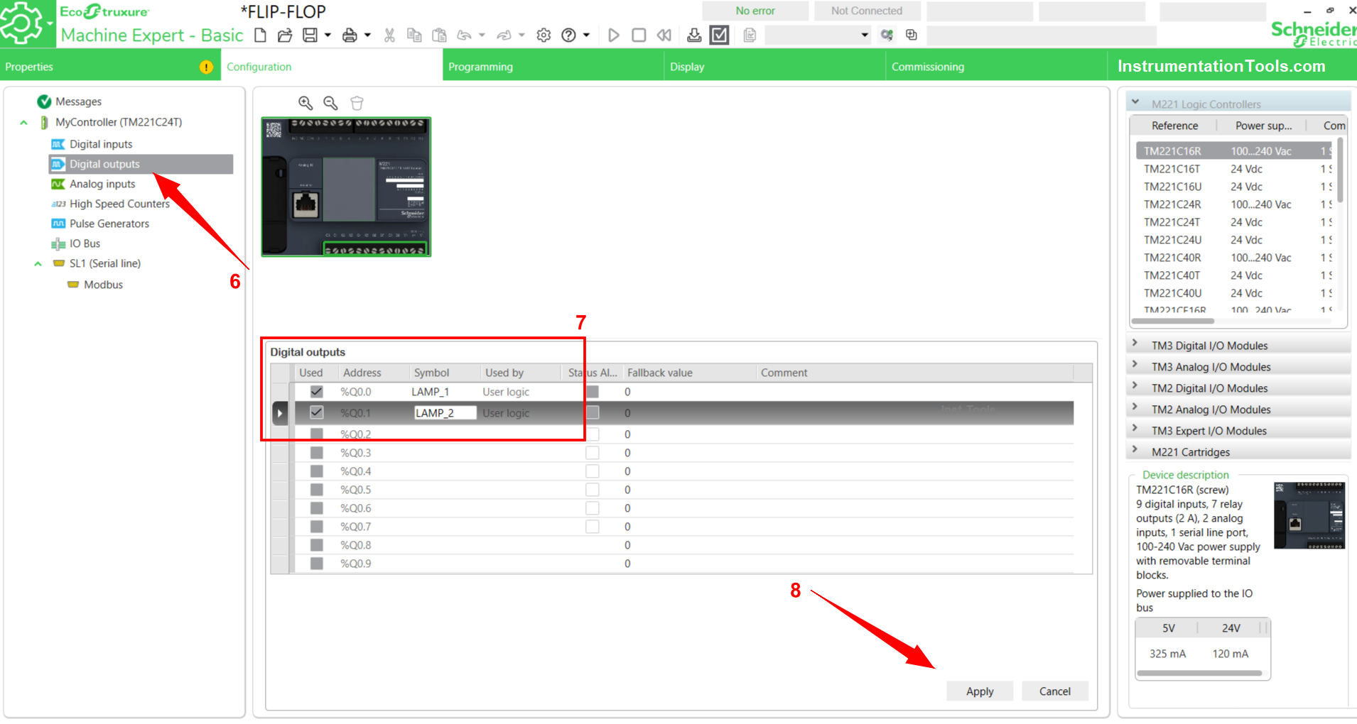
Just like the method in setting Digital Input, we need to click the Digital Output Sub menu then a list of Digital Output parameters will appear on the work page.
Give a name/label to the SYMBOL column, in this program using 2 Digital Output contacts with names/labels LAMP_1, LAMP_2. We can also add a description of each address in the comment field.
When finished, click the “Apply” button to apply the settings that have been done. In Ecostruxure Machine-Basic Software, the Digital address output address uses the format %Q0.0 – %Q0.xxx.
The next step is to enter the Programming Sub menu to create a Program. Create a Program as follows.
Flip-Flop PLC Program for Lamps Application
NETWORK 0
In this rung, there are 3 NO(Normally Open) contacts from PB_START (I0.0), IR_MASTER (%M0) and IR_TIMER_0 (%M1), 4 NC (Normally Close) contacts from PB_STOP (%I0.1), IR_COUNTER (%M3), and IR_TIMER_1 (%M2), 3 Bit Memory Coils IR_MASTER (%M0), IR_TIMER_0 (%M1), and IR_TIMER_1 (%M2).
When PB_START (I0.0) is activated momentarily, it turns ON the Bit Memory Coil IR_MASTER (%M0). At the same time, TIMER_0 (%TM0) will start calculating until it reaches its Preset value.
When TIMER_0 (%TM0) has reached its Preset value, it activates TIMER_1(%TM1) and turns ON the Bit Memory Coil IR_TIMER_0 (%M1). When TIMER_1 (%TM1) has reached its Preset value, it activates the Bit Memory Coil IR_TIMER_1 (%M2).
The Bit Memory Coil IR_TIMER_1 (%M2) will only activate for a moment and instantly cut OFF the incoming signal flow to the TIMER_0 (%TM0) using its NC (Normally Close) contacts.
The system will not stop if PB_START is turned OFF, the system will still run because of the Latching function of Bit Memory IR_MASTER (%M0). The system will stop only if PB_STOP (%I0.1) is enabled, and IR_COUNTER(%I0.2) is ON.
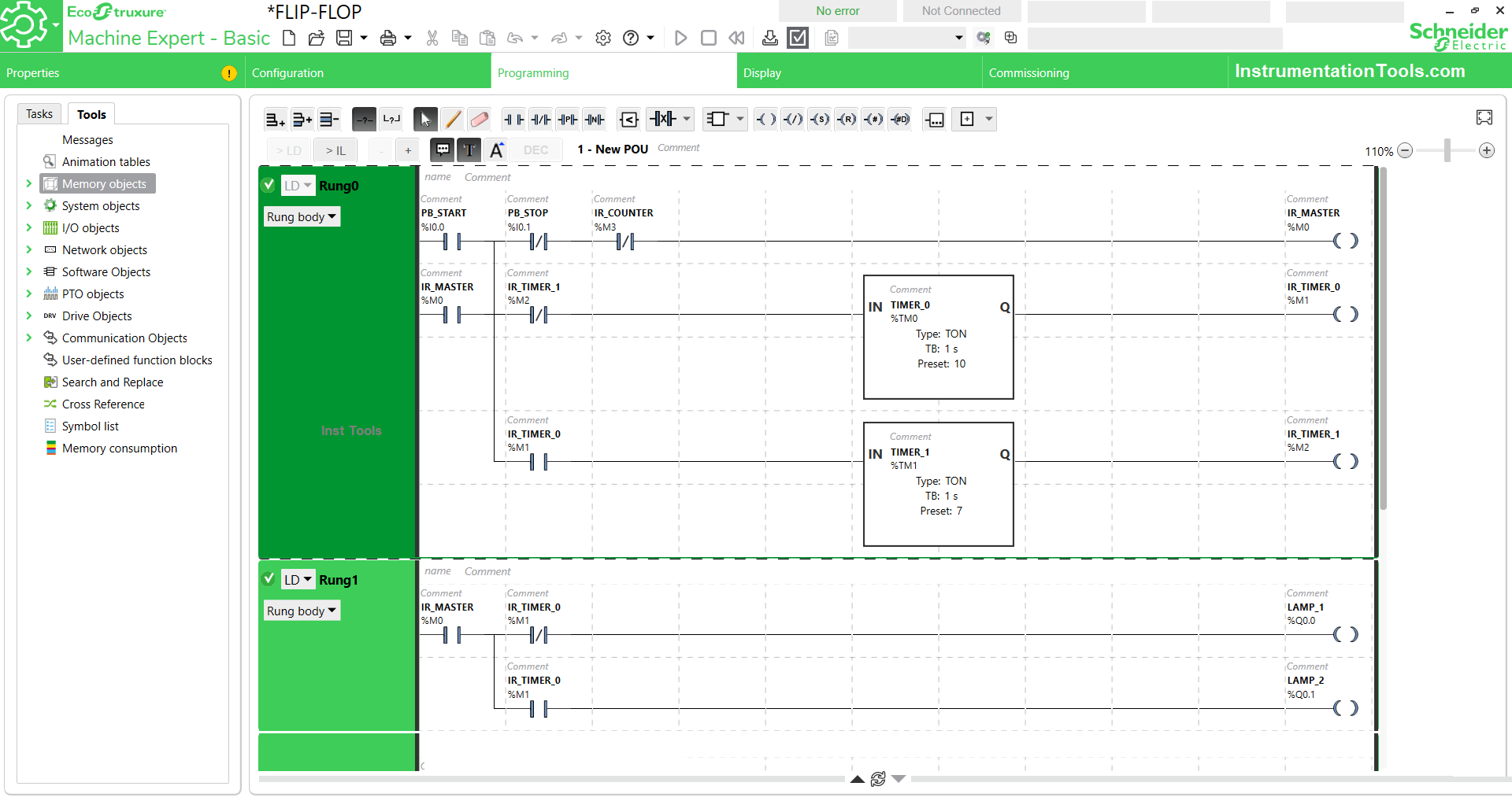
NETWORK 1
In Rung 1, there are 2 NO (Normally Open) contacts from IR_MASTER (%M0) and IR_TIMER_0 (%M1), 1 NC (Normally Close) contact from IR_TIMER_0 (%M1), 2 Digital Output Coils from LAMP_1 (%Q0.0) and LAMP_2 (%Q0.1).
When the NO (Normally Open) IR_MASTER (%M0) contact is active simultaneously it will also activate LAMP_1 (Q0.0), while LAMP_2 (%Q0.1) will be active when there is a change in the Bit Memory logic value IR_TIMER_0 (%M1) to “True”.
LAMP_1 (%Q0.0) and LAMP_2 (%Q0.1) will work interchangeably because they use the same Bit Memory address which is IR_TIMER_0 (%M1) but uses a different type of contact, LAMP_1 (%Q0.0) uses the NC (Normally Close) contact and LAMP_2 (%Q0.1) uses the NO (Normally Open) contact.
NETWORK 2
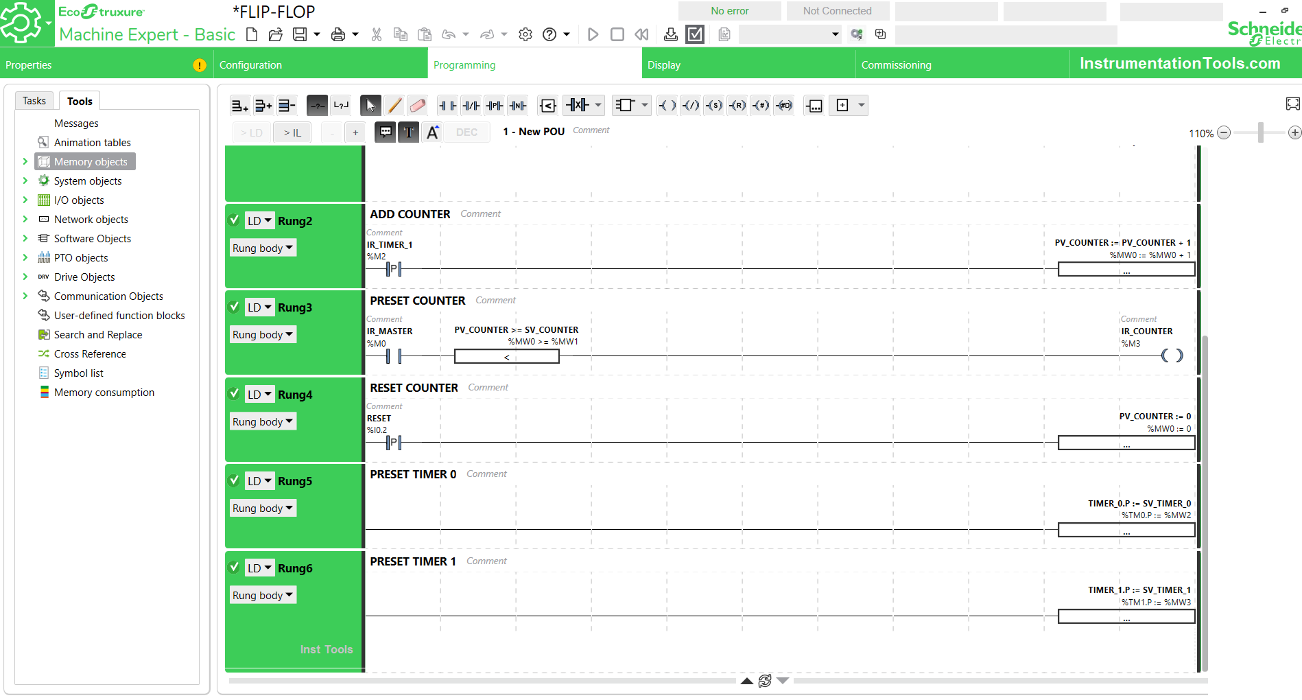
This rung serves as a counter area. There is 1 Rising Edge type NO (Normally Open) contact with Bit Memory address IR_TIMER_1 (%M2) and Operation Block with the function “%MW0:= %MW0+1”.
When the NO (Normally Open) contact of IR_TIMER_1 (M2) is active, the Operation Block will move data from PV_COUNTER (%MW0)+1 into the PV_COUNTER address (%MW0), so that every NO (Normally Open) contact from IR_TIMER_1 (M2) is active, the data at the PV_COUNTER address (%MW0) will increase by 1.
This way the Rising Edge type NO (Normally Open) Contact works is that when the contact is activated, it will channel a signal of 1 pulse wave at the beginning of the button is activated and immediately turns OFF. Thus eliminating the possibility of the amount of data entering the PV_COUNTER (%MW0) more than 1 time.
NETWORK 3
In RUNG 3, there is 1 NO (Normally Open) contact from IR_MASTER (%M0), 1 Operation Block with %MW0>=%MW1 function, and 1 Coil IR_COUNTER (%M3).
The NO (Normally Open) contact of the activated IR_MASTER (%M0) will send a signal to the Coil IR_COUNTER(%M3) when the value at PV_COUNTER (%MW0) is greater than or equal to SV_COUNTER (%MW1).
SV_COUNTER (%MW1) serves as a comparison reference data from PV_COUNTER (%MW0) so that when the PV_COUNTER value (%MW0) is greater than or equal to SV_COUNTER (%MW1) it will turn ON the Coil IR_COUNTER (%M3) which causes the system to stop, because of the Interlock function of the IR_COUNTER( %M3) in RUNG 1.
SV_COUNTER (%MW1) also functions as Preset Counter data commonly called Set value, so we can enter data on the SV_COUNTER (%MW1) as we wish.
NETWORK 4
This rung serves to reset the Counter data in the PV_COUNTER (%MW0).
There is 1 NO (Normally Open) contact of RESET (I0.2) and 1 Operation Block with %MW0:=0 Function.
This means that for every contact NO (Normally Open) of RESET (I0.2) is active, the Operation Block will move the value “Zero” to PV_COUNTER (%MW0).
NETWORK 5
Rung 5 only has an Operation Block that functions as a preset value adjuster of TIMER_0 (%TM0).
When the data is entered into SV_TIMER_0 (%MW2) it will be moved into Preset data TIMER_0 (%TM0).
NETWORK 6
Rung 6 only has an Operation Block that functions as a preset value adjuster of the TIMER_1 (%TM1) value.
When the data is entered into SV_TIMER_1 (%MW3), it will be moved into Preset data TIMER_1 (%TIM1).
If you liked this article, please subscribe to our YouTube Channel for PLC and SCADA video tutorials.
You can also follow us on Facebook and Twitter to receive daily updates.
Read Next:
- Digital Electronics Objective Questions
- How to Blink Lights in PLC Ladder Logic?
- Electrical Ladder Diagram Control with Timers
- PLC Control a Pump based on Level Sensors
- Design flip-flop using other flip-flops Questions