What is a Substation?
In the process of electricity generation, transmission and distribution, the voltage needs to be transformed from low to high or high to low as per different requirements. A switching station where this transformation takes place using transformers is known as a SubStation. When this switching station is in a Power House, it is called Switchyard.
Types of Substations
Substations may be classified on the basis of purpose and location of construction. Depending on the purpose, there are Step-up substations, Primary Grid substations, Secondary substations, Distribution substations, etc.
Depending on the location of construction there are Outdoor substations, Indoor substations, Underground substations, Pole mounted substations.
Busbar Arrangements
There are various kinds of Busbar arrangements adopted for different Substations as per specific requirements.
Some of the factors guiding the selection of the arrangement are voltage level, reliability of supply, flexibility, and cost.
Some busbar arrangements commonly used are –
- Single Busbar, Single Busbar with Bus coupler
- Main & Transfer Bus
- Double Busbar, Double BusBar with Bypass
- Double Main and Transfer Busbar Scheme
- One & Half Circuit Breaker
- Ring and Mesh Busbar
Single Busbar Scheme
In this scheme, each circuit is provided with one circuit breaker, two isolators on both sides, and a current transformer. It is the simplest and cheapest scheme.
Its limitation is that maintenance of bus and/or circuit breakers cannot be carried out without interrupting the supply.
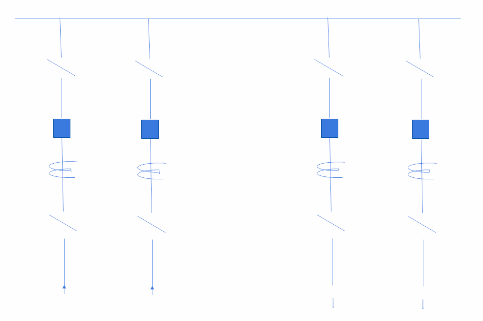
The limitation of the Single Bus Scheme is overcome by sectionalizing the bus using a bus coupler. By doing this each section acts as an individual bus and maintenance can be carried out without a complete shutdown of the system.
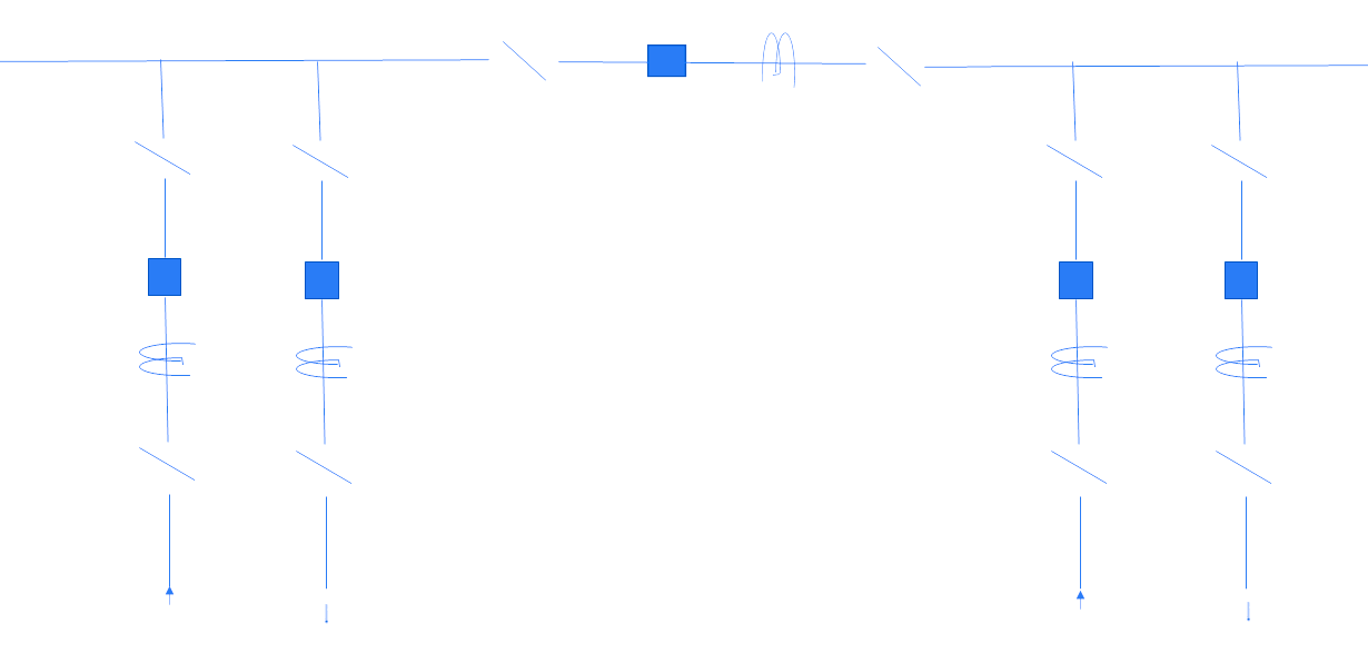
Main and Transfer Busbar
In this scheme, there is an additional transfer busbar along with the main busbar.
When any circuit breaker needs to be taken out for maintenance, its load is transferred to the transfer busbar and the power travels to the main busbar through a bus coupler.
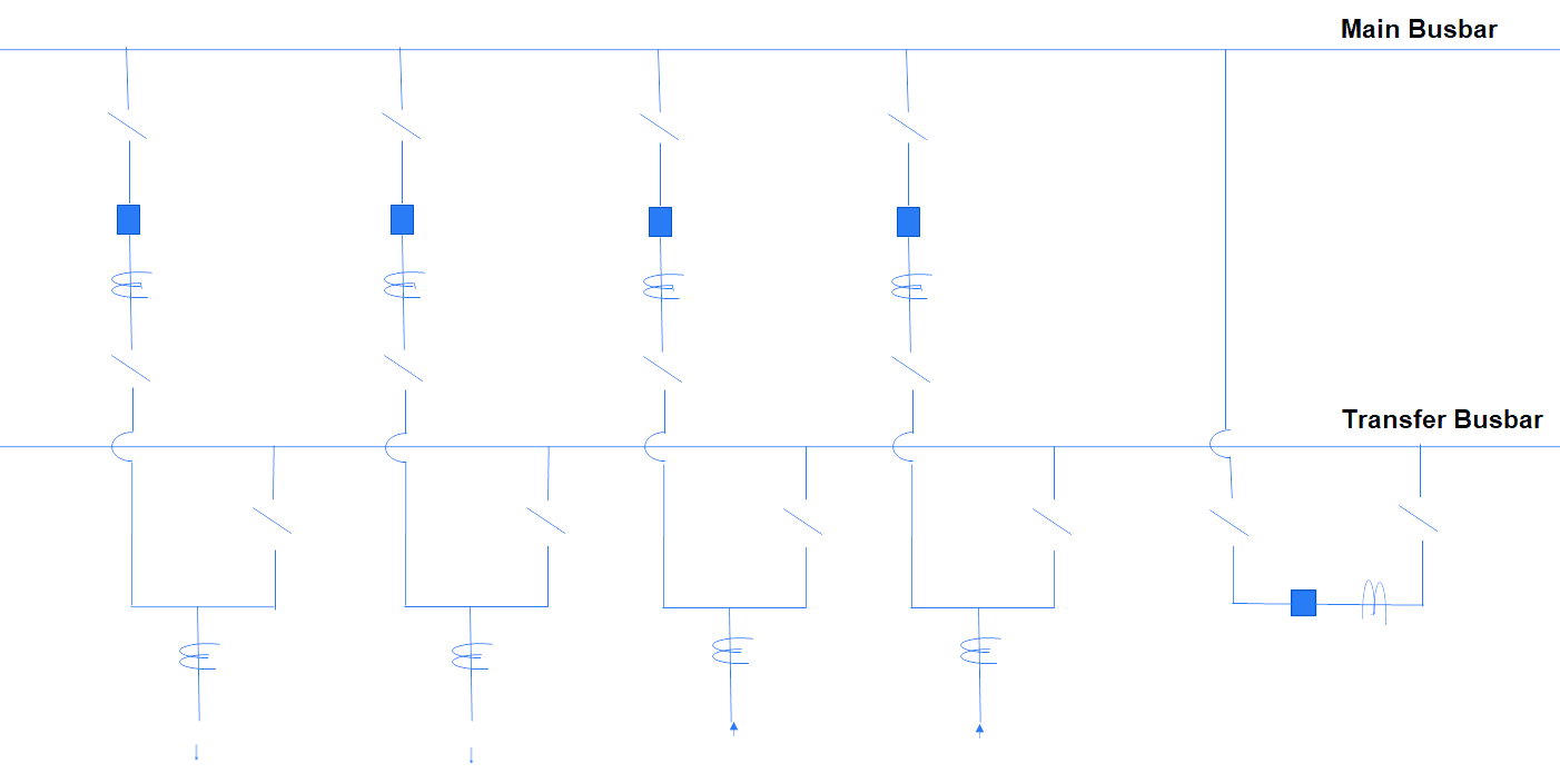
This way circuit breaker maintenance is possible without interrupting the supply. However, bus maintenance cannot be carried out without a complete shutdown of the system.
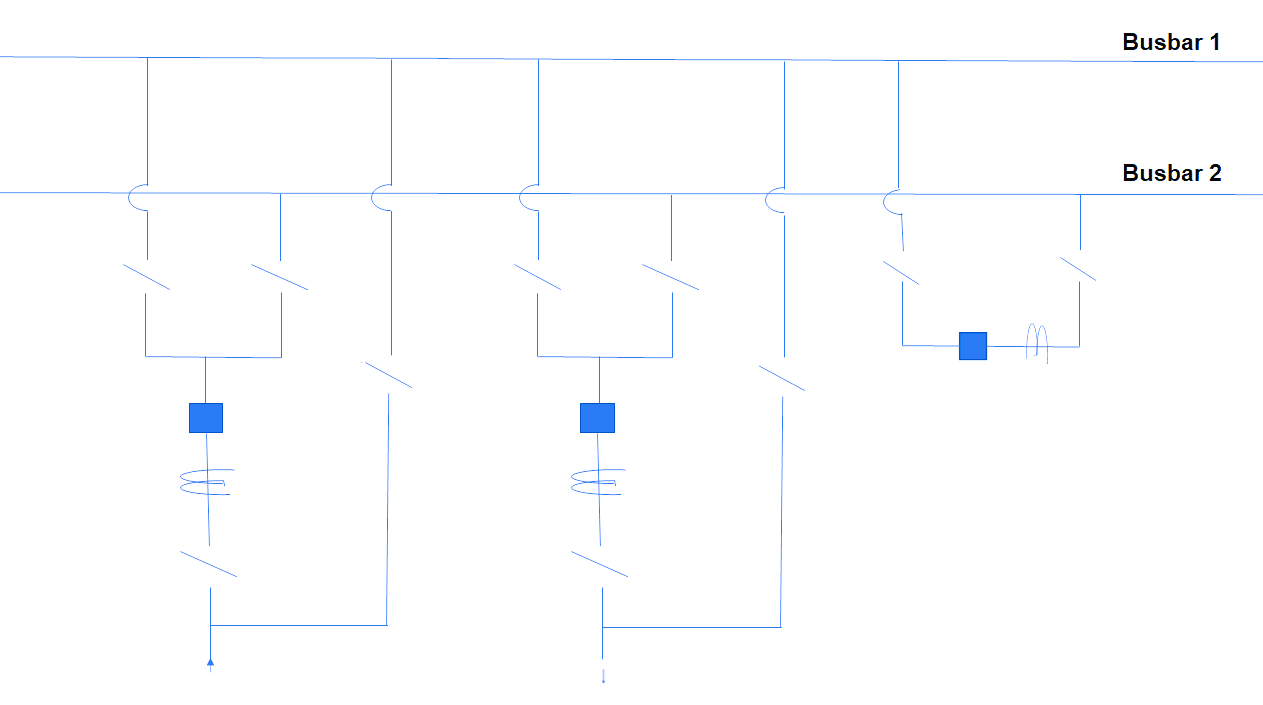
Double Busbar
There are two busbars in this scheme and the load can be connected to any of the busbars through isolators.
A bus coupler is also provided for the transfer of load from one busbar to another. The limitation of this scheme is that the feeder is to be shut down when its circuit breaker is under maintenance.
This limitation is overcome by connecting a bypass isolator to one of the main busbar.
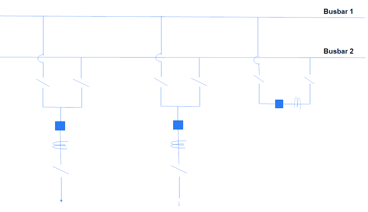
The limitation of this scheme is that the feeder is to be shut down when its circuit breaker is under maintenance.
This limitation is overcome by connecting a bypass isolator to one of the main busbar.
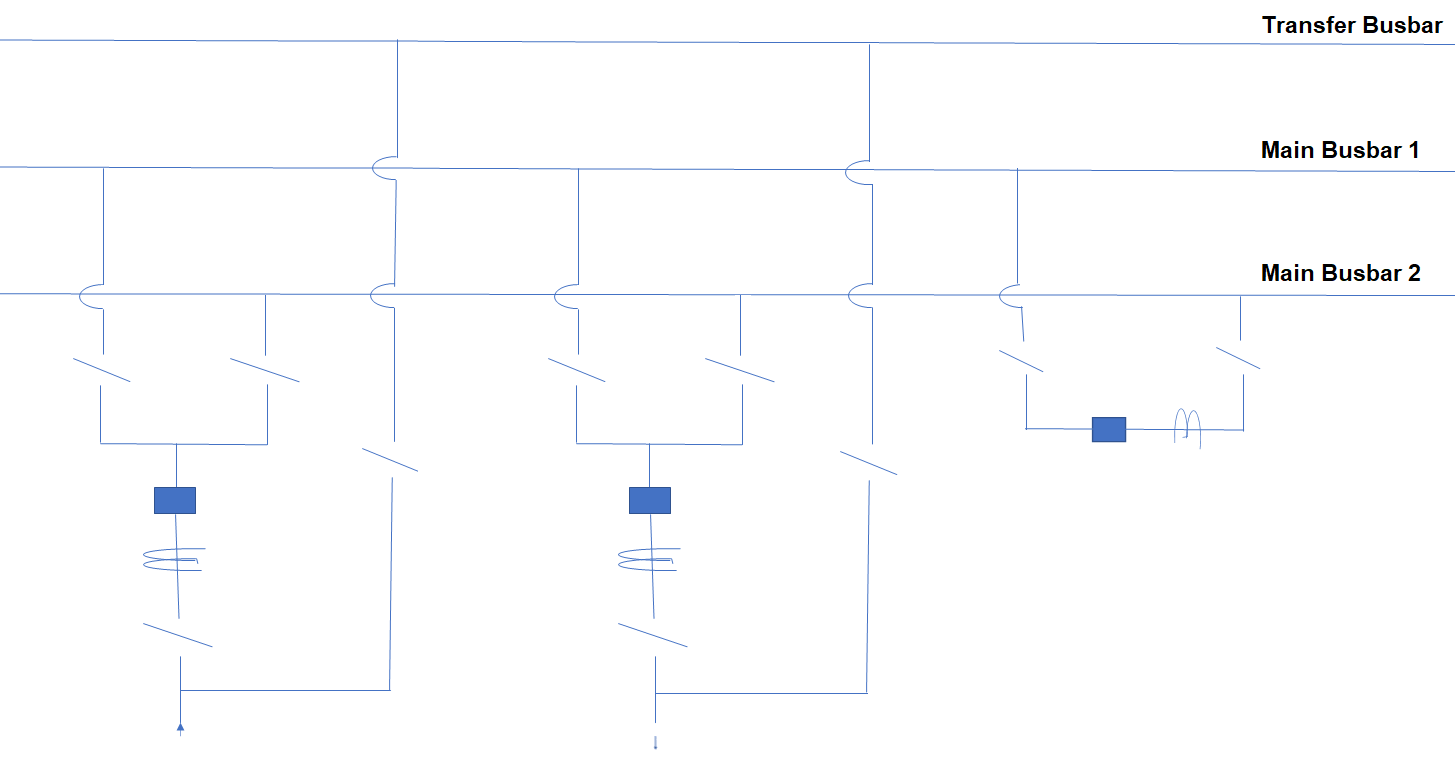
Double Main and Transfer Busbar Scheme
In this scheme, there are two main busbars with an additional transfer busbar.
When a circuit breaker is out for maintenance, its load is transferred to the transfer busbar and controlled through the bus coupler, without affecting the other feeders.
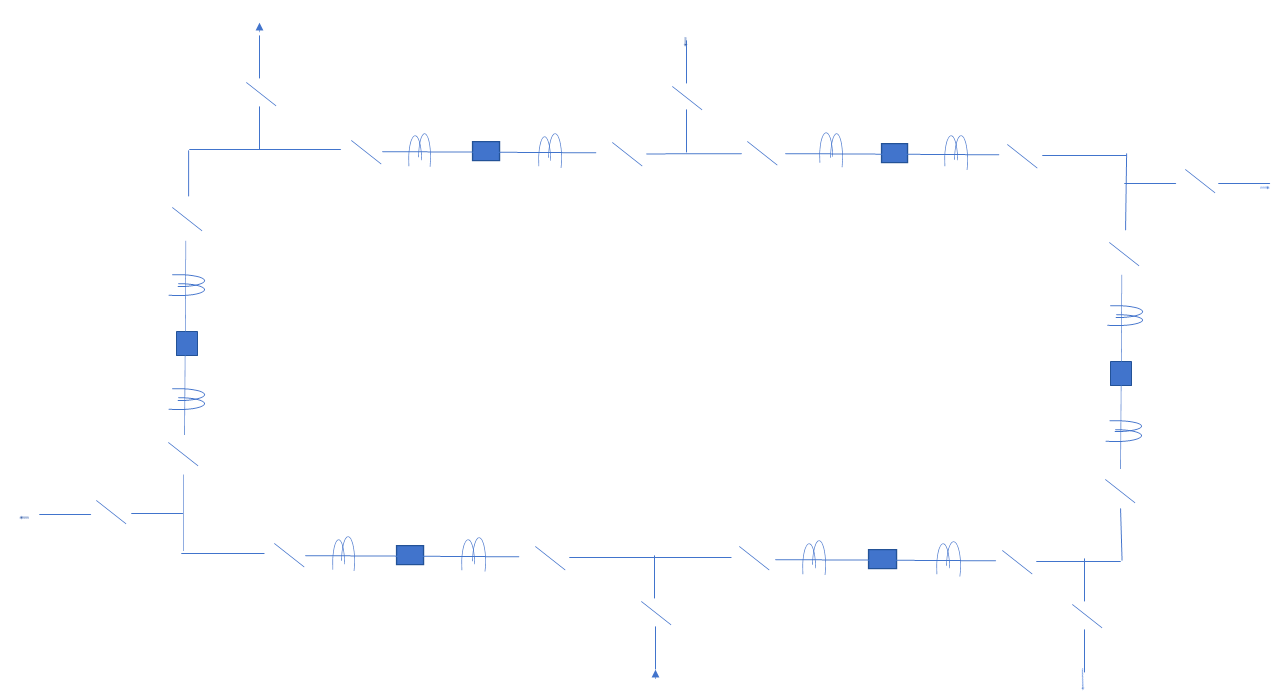
Mesh Busbar Scheme
In this scheme, a mesh is formed of all the busbars and two circuit breakers are connected in each circuit.
Maintenance of any circuit breaker is possible without interruption in supply.
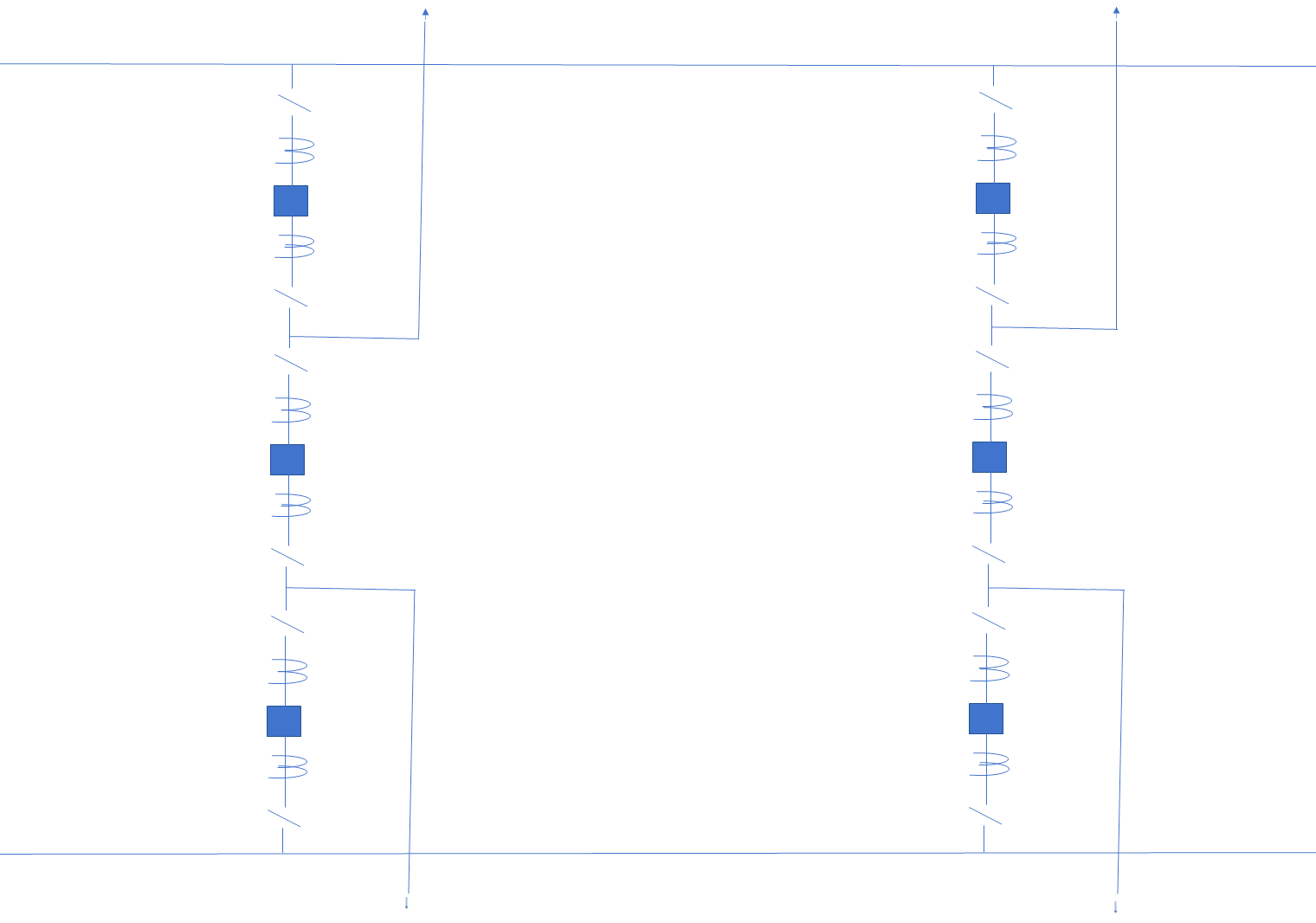
Breaker and a Half Scheme
In this scheme, three circuit breakers are used for every two circuits i.e only one spare breaker is provided for two circuits.
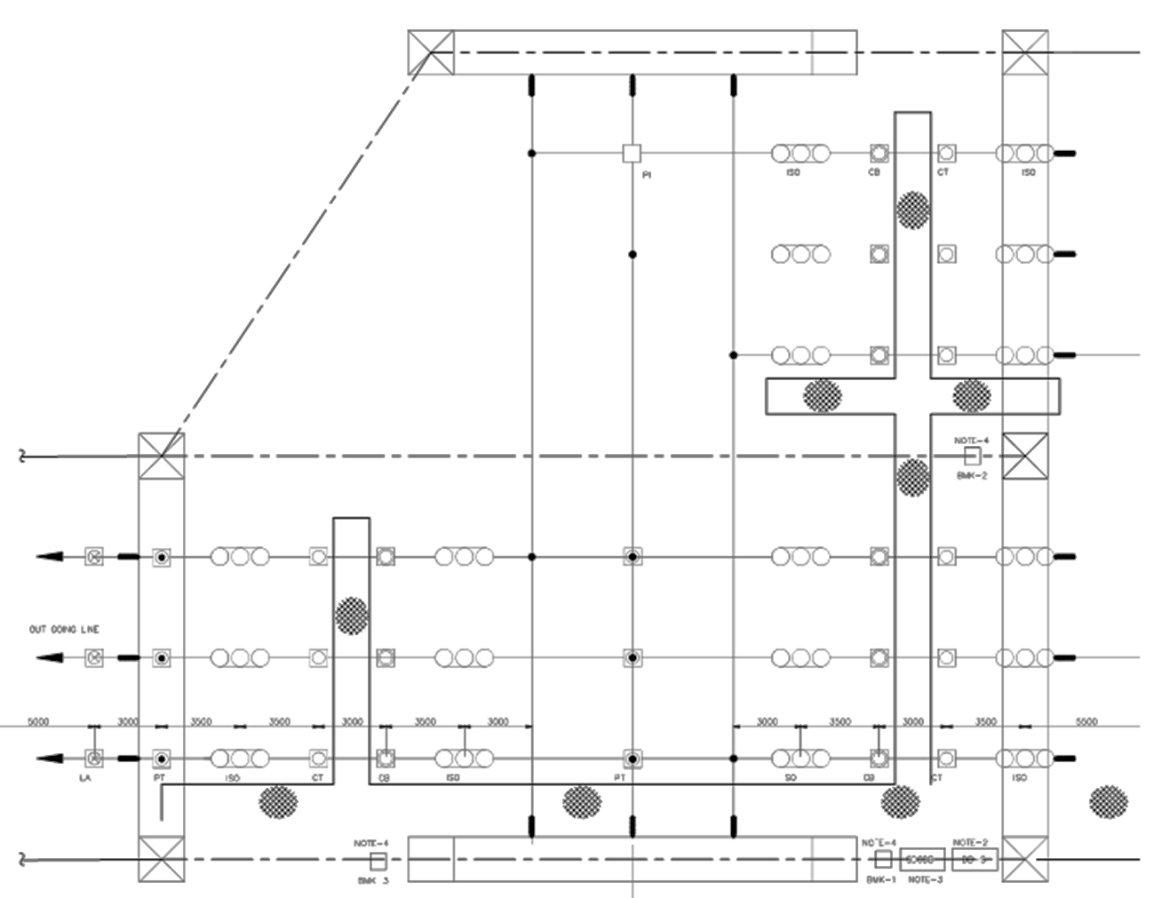
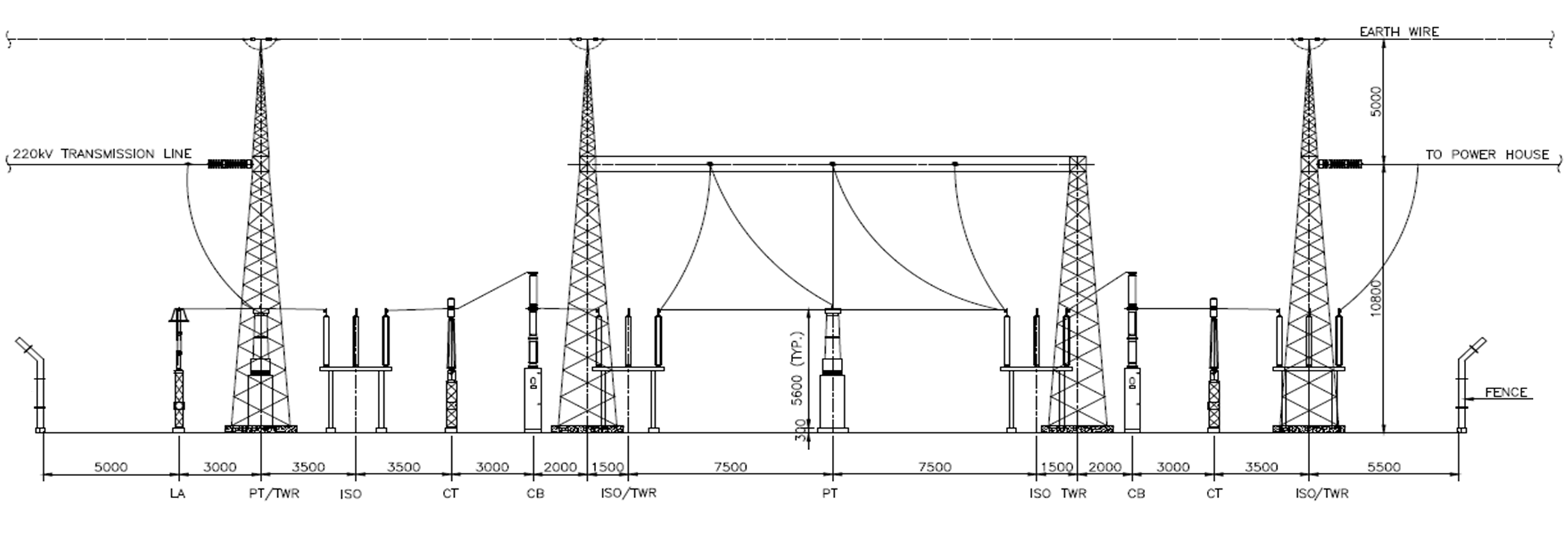
Electrical Layout Drawings
Layout drawings showing the actual positions of all equipment are prepared after deciding on the busbar arrangement.
Depending upon the area available, the best possible electrical layout is prepared which takes into consideration phase to phase clearance, phase to ground clearance and shows the actual position of all equipment.
Layout designing shall be done diligently maintaining proper electrical clearances to ensure satisfactory performance of system and safety of working personnel.
A typical layout of a switchyard is shown below:
Author: Nitin Kumar
If you liked this article, then please subscribe to our YouTube Channel for Instrumentation, Electrical, PLC, and SCADA video tutorials.
You can also follow us on Facebook and Twitter to receive daily updates.
Read Next:
What is a Link Box?
Static UPS and Rotary UPS
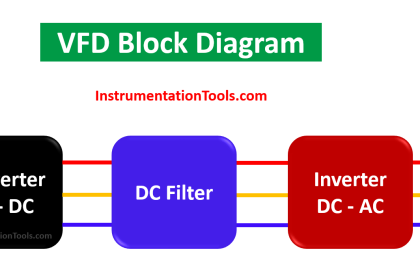
Commissioning of VFD Drive
DOL Starter Working Principle
Motor Forward Reverse Control