Inst ToolsInst ToolsInst Tools
  • Courses
  • Automation
    • PLC
    • Control System
    • Safety System
    • Communication
    • Fire & Gas System
  • Instrumentation
    • Design
    • Pressure
    • Temperature
    • Flow
    • Level
    • Vibration
    • Analyzer
    • Control Valve
    • Switch
    • Calibration
    • Erection & Commissioning
  • Interview
    • Instrumentation
    • Electrical
    • Electronics
    • Practical
  • Q&A
    • Instrumentation
    • Control System
    • Electrical
    • Electronics
    • Analog Electronics
    • Digital Electronics
    • Power Electronics
    • Microprocessor
  • Request
Search
  • Books
  • Software
  • Projects
  • Process
  • Tools
  • Basics
  • Formula
  • Power Plant
  • Root Cause Analysis
  • Electrical Basics
  • Animation
  • Standards
  • 4-20 mA Course
  • Siemens PLC Course
Reading: Current Transformer Selection, Operation & Maintenance
Share
Font ResizerAa
Inst ToolsInst Tools
Font ResizerAa
  • Courses
  • Design
  • PLC
  • Interview
  • Control System
Search
  • Courses
  • Automation
    • PLC
    • Control System
    • Safety System
    • Communication
    • Fire & Gas System
  • Instrumentation
    • Design
    • Pressure
    • Temperature
    • Flow
    • Level
    • Vibration
    • Analyzer
    • Control Valve
    • Switch
    • Calibration
    • Erection & Commissioning
  • Interview
    • Instrumentation
    • Electrical
    • Electronics
    • Practical
  • Q&A
    • Instrumentation
    • Control System
    • Electrical
    • Electronics
    • Analog Electronics
    • Digital Electronics
    • Power Electronics
    • Microprocessor
  • Request
Follow US
All rights reserved. Reproduction in whole or in part without written permission is prohibited.
Inst Tools > Blog > Electrical Basics > Current Transformer Selection, Operation & Maintenance

Current Transformer Selection, Operation & Maintenance

Last updated: December 20, 2015 2:04 pm
Editorial Staff
Electrical Basics
1 Comment
Share
5 Min Read
SHARE

Current Transformer: For Selection, Operation, and Inspection & Maintenance

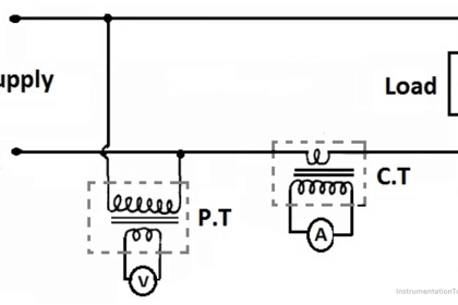
In general, large currents (hundreds of amperes) cannot be directly input to powermeters for measuring power. Therefore, the current is passed through a CT (current transformer) prior to measurement. The following are some points regarding selection, operation, and maintenance of CTs.
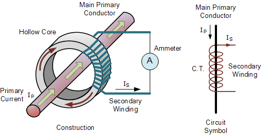
Current Transformer Operation

Selecting a CT

  1. Check the voltage of the circuit.
    Check the voltage of the circuit to be tested, then select a CT that supports that voltage.
  2. Check the rated primary current.
    Choose a CT with a rated primary current that is slightly larger than the maximum current that will be measured (ex.: 100 A, 200 A, 300 A, 500 A, 800 A). The rated secondary current is typically 5 A, but there are also 1-A transformers. Single ampere CTs are useful for long-distance wiring.
  3. Check the rated load.
    The load should be checked because it affects the wiring distance and other factors. See, “Operating a CT.”
  4. Ampere-turn:Current Transformer PrincipleIf the primary current is a few amperes, winding the primary cable around the CT several times will cause the secondary current to be multiplied by just the number of times the cable is wound, allowing you to extract it. For example, if you wind a cable once around a 100 A/1 A CT, two turns of the cable will pass through the center of the CT resulting in a 50 A/1 A ratio.
  5. Other:
    To prevent accidents when the secondary circuit is open, it is safest to use a CT with a built-in voltage restraint.

Operating a CT

    1. The rated load is the sum of the distribution loss between the CT and instrument connected to the Current Transformer Workingsecondary side, and the insertion loss at the instrument connected to the secondary side. You should keep the value within this load rating, for example, an indication of 0.5 VA or 2.5 VA.
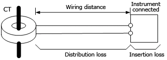
      CT rated load ≥ distribution loss + insertion loss at secondary side

      To calculate the distribution loss, see (2) and (3) below.

    2. Check the wiring distance and material.
      Loss grows proportionally larger with the wiring distance.
      The total length of the wiring materials is the distance both ways.

      Approx. Resistance in Wiring Material
      Nominal cross-sectional area: 1.25 mm²= Approx. 18 Ω/km
      Nominal cross-sectional area: 2.0 mm² = Approx. 10 Ω/km

    3. Examples (rough calculation)

      CT: rated primary current/rated secondary current = 100 A/1 A
      CT’s rated load: 0.5 VA

      • When using wiring material with a nominal cross-sectional area of 1.25 mm²

        Wiring resistance R = 18 Ω/km × 0.015 km × 2 (both ways) = 0.54 Ω
        Distribution loss ≈ I²R = (rated secondary current)² × wiring resistance = 1 × 1 × 0.54 = 0.54 VA
        Condition: CT rated load > distribution loss + insertion loss of the instrument connected to the secondary side
        This results in 0.5 < 0.54 + 0.2 = 0.74, which is false (the condition is not met).

      • When using wiring material with a nominal cross-sectional area of 2.0 mm2

        Wiring resistance R = 10 Ω/km × 0.015 km × 2 = 0.3 Ω
        Distribution loss ≈ I²R = (rated secondary current)² × wiring resistance = 1 × 1 × 0.3 = 0.3 VA
        Condition: CT rated load > distribution loss + insertion loss of the instrument connected to the secondary side
        This results in 0.5 ≥ 0.3 + 0.2 = 0.5, which is true (the condition is met).
        In the example above, wiring with a nominal cross-sectional area of 2.00 mm2 is required.

Precautions Regarding Inspection and Maintenance

Never work on live wires. High voltage is generated when current is flowing through the CT and the secondary circuit is open. It is extremely dangerous to leave the device is a state in which dielectic breakdown seems likely to occur, as burns or fires can result. Therefore, always short the CT’s secondary circuit before turning on the electricity after performing maintenance. Recently, CTs with built-in voltage restraints for the secondary circuit have become available.
Don't Miss Our Updates
Be the first to get exclusive content straight to your email.
We promise not to spam you. You can unsubscribe at any time.
Invalid email address
You've successfully subscribed !

Continue Reading

Types of Stepper Motors
Download Electrical Enclosure Book
Electrical Components Overheating – Causes, Troubles, Prevent
Difference Between Contactor and Relay
Difference Between Open Circuit and Close Circuit
What are Static UPS and Rotary UPS?
Share This Article
Facebook Whatsapp Whatsapp LinkedIn Copy Link
Share
1 Comment
  • Yahya Ansari says:
    May 26, 2018 at 3:10 am

    Thank you for giving me excellent knowledge about CT.
    I learn more knowledge by you.

    Reply

Leave a Reply Cancel reply

Your email address will not be published. Required fields are marked *

Stay Connected

128.3kFollowersLike
69.1kFollowersFollow
210kSubscribersSubscribe
38kFollowersFollow

Categories

Explore More

Electrical Contactor Interlocking Circuit Explained
What is Electrical Conduit? Types, Advantages, Disadvantages
Electrical Cabinet Air Conditioner – Enclosure Cooling, Maintenance
Contactor – Basics, Wiring, Connection with PLC
Star Delta Starter – Working, Circuit, Advantages, Disadvantages
Electrical Power Grid Automation
Difference Between Isolator and Circuit Breaker
All About Electric Fence Gates

Keep Learning

Allen-Bradley VFD

Motor VFD Drive features

corroded tank

Cathodic Protection – Sacrificial Anodic and Impressed Current

Variable-speed motor controls

Variable Motor Speed Control

What is an Instrument Transformer?

What is an Instrument Transformer? – Types, Principle, Advantages

Electrical Equipment Selection in Hazardous Area

Hazardous Areas in Industry – Electrical Equipment Selection

SCADA in Power System

Electrical Energy Management System and SCADA in Power System

Why Do We Need to Connect Transformers in Parallel

Why Do We Need to Connect Transformers in Parallel?

Components of Electrical Motor

What is Electrical Slip Ring? Principle, Types, Advantages, Applications

Learn More

Ion Spectrometers Questions & Answers

Ion Spectroscopy Questions & Answers

Magnetic Level Indicator

Magnetic Level Indicator Principle, Limitations, Installation and Calibration

Optimal Control Systems

The Infinite Time Regulator Problem

Distributed Control System Architecture for Foundation Fieldbus Field Instruments

What is Foundation Fieldbus (FF) ?

Ion Analyzers Questions and Answers

Ammonia and Fluoride Electrode Questions & Answers

Forward Bias

Rectifiers, Forward Bias and Reverse Bias

Parts of PLC

Parts of PLC

Controlling of Tank Level Using Proportional Controller in PLC

Controlling of Tank Level Using Proportional Controller in PLC

Menu

  • About
  • Privacy Policy
  • Copyright

Quick Links

  • Learn PLC
  • Helping Hand
  • Part Time Job

YouTube Subscribe

Follow US
All rights reserved. Reproduction in whole or in part without written permission is prohibited.
Welcome Back!

Sign in to your account

Username or Email Address
Password

Lost your password?