Inst ToolsInst ToolsInst Tools
  • Courses
  • Automation
    • PLC
    • Control System
    • Safety System
    • Communication
    • Fire & Gas System
  • Instrumentation
    • Design
    • Pressure
    • Temperature
    • Flow
    • Level
    • Vibration
    • Analyzer
    • Control Valve
    • Switch
    • Calibration
    • Erection & Commissioning
  • Interview
    • Instrumentation
    • Electrical
    • Electronics
    • Practical
  • Q&A
    • Instrumentation
    • Control System
    • Electrical
    • Electronics
    • Analog Electronics
    • Digital Electronics
    • Power Electronics
    • Microprocessor
  • Request
Search
  • Books
  • Software
  • Projects
  • Process
  • Tools
  • Basics
  • Formula
  • Power Plant
  • Root Cause Analysis
  • Electrical Basics
  • Animation
  • Standards
  • 4-20 mA Course
  • Siemens PLC Course
Reading: DP Transmitter Dry Leg & Wet Leg Calculations
Share
Font ResizerAa
Inst ToolsInst Tools
Font ResizerAa
  • Courses
  • Design
  • PLC
  • Interview
  • Control System
Search
  • Courses
  • Automation
    • PLC
    • Control System
    • Safety System
    • Communication
    • Fire & Gas System
  • Instrumentation
    • Design
    • Pressure
    • Temperature
    • Flow
    • Level
    • Vibration
    • Analyzer
    • Control Valve
    • Switch
    • Calibration
    • Erection & Commissioning
  • Interview
    • Instrumentation
    • Electrical
    • Electronics
    • Practical
  • Q&A
    • Instrumentation
    • Control System
    • Electrical
    • Electronics
    • Analog Electronics
    • Digital Electronics
    • Power Electronics
    • Microprocessor
  • Request
Follow US
All rights reserved. Reproduction in whole or in part without written permission is prohibited.
Inst Tools > Blog > Formulas > DP Transmitter Dry Leg & Wet Leg Calculations

DP Transmitter Dry Leg & Wet Leg Calculations

Last updated: March 24, 2020 9:55 am
Editorial Staff
Formulas Guest Articles Level Measurement
26 Comments
Share
4 Min Read
SHARE

In any process industry, level measurement is very important for safety and process purpose.

Contents
DP Transmitter Level Measurement for Closed TankDry leg method:Wet leg method:DP Transmitter Level Measurement for Closed Tank – Dry Leg MethodDP Transmitter Level Measurement for Closed Tank – Wet Leg Method

The level can be measured by two methods.

  1. Direct method
  2. Indirect method

Here we discuss the indirect method and which is using DP transmitter for level measurement.

A Differential pressure transmitter is a common and well-understood technology for liquid level measurement. If the tank is closed or pressurized, a DP measurement must be made to compensate for the vessel pressure.

DP Transmitter Level Measurement for Closed Tank

In closed tank DP level measurement,  LP leg is connected to the top of tank.

There are two methods in closed tank DP Level Measurement.

Dry leg method:

Dry leg method is used in normal close tank where vapor is not condensate and temperature of process is equal to atmospheric.

Wet leg method:

Wet leg method is used where vapor has a tendency to make the condensate and temperature of process is high or low from the atmospheric .

For DP Transmitter Configuration, we have to find out Zero Level & Span Level. Accordingly we have to configure Lower Range Value (LRV) and Upper Range Value (URV) using HART communicator.

DP Transmitter Level Measurement for Closed Tank – Dry Leg Method

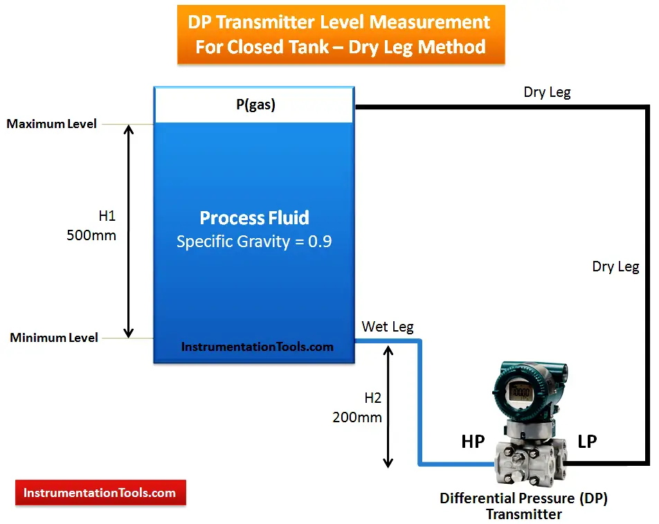
Simply when LP side of the DP transmitter is filled with any gas/air then we call it as Dry Leg & we apply Dry Leg Method for calculations.

DP Transmitter Level Measurement for Closed Tank Dry leg Method

At zero level (LRV) = pressure acting on HP leg – Pressure acting on LP leg

=H2 x specific gravity – 0

= 200 x 0.9 – 0

= 180 mmwc

At 100 % level (URV) = pressure acting on HP leg – Pressure acting on LP leg

= (H2+H1) x specific gravity – 0

= (200 + 500) x 0.9 – 0

= 630 mmwc

Range = URV – LRV = 630 – 180 mmwc = 450 mmwc

So, we have to set Lower Range Value (LRV) = 180 mmwc and Upper Range Value (URV) = 630 mmwc in the DP Transmitter using HART communicator.

DP Transmitter Level Measurement for Closed Tank – Wet Leg Method

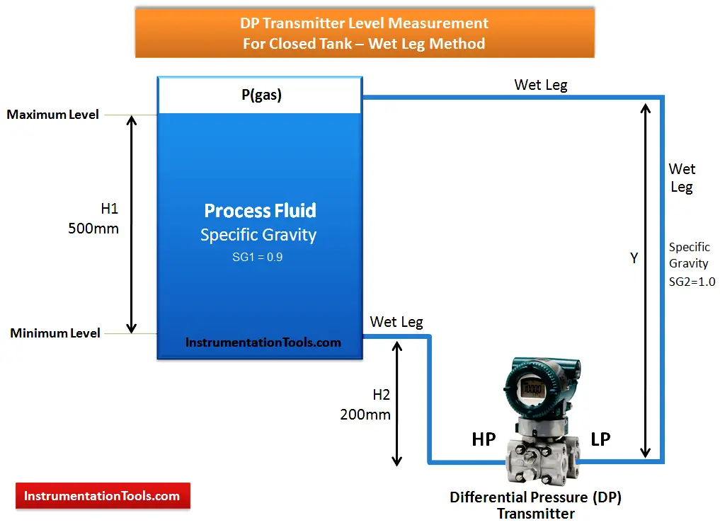
Simply when LP side of the DP transmitter is filled with liquid then we call it as Wet Leg & we apply Wet Leg Method for calculations.

DP Transmitter Level Measurement for Closed Tank Wet leg Method

Y = H1 +H2 = 500 + 200 = 700 mm
At zero level (LRV) = pressure acting on HP leg – Pressure acting on LP leg

= H2 x SG1 – Y x SG2

= 200 x 0.9 – 700 x 1.0

= 180 – 700

= – 520 mmwc

At 100 % level (URV) = pressure acting on HP leg – Pressure acting on LP leg

= (H2+H1) x SG1 – Y x SG2

= (200 + 500) x 0.9 – 700 x 1.0

 = 630 – 700

= -70 mmwc

Range = URV – LRV = -70 – (-520) = 450 mmwc

So, we have to set Lower Range Value (LRV) = -520 mmwc and Upper Range Value (URV) = -70 mmwc in the DP Transmitter using HART communicator.

Author: Ashish Agrawal

Articles You May Like:

  • Tank DP Level Transmitter 
  • Float level switch
  • Paddle Wheel Level Switch
  • Boiler Drum Level Transmitter
  • DP Transmitter Auto Calibration
Don't Miss Our Updates
Be the first to get exclusive content straight to your email.
We promise not to spam you. You can unsubscribe at any time.
Invalid email address
You've successfully subscribed !

Continue Reading

Conductive Level Measurement Working Principle
How a Level Switch Works
Instrument Panel Cooling Efficiency Enhancement
Ultrasonic Level Measurement
Zero Suppression and Zero Elevation Calculations
Magnetic Level Gauge Working Principle Animation
Share This Article
Facebook Whatsapp Whatsapp LinkedIn Copy Link
Share
26 Comments
  • Ahmed Saadoon says:
    March 24, 2018 at 9:13 am

    Dear Sir
    I have question, why you neglect the LP side When you do a calculation on a dry leg mode? could you explaine that to me please?

    Best regards
    Ahmed

    Reply
    • azetou says:
      March 25, 2018 at 10:31 am

      when we consider a dry leg, it means that LP side is subject to only Vapor / gas pressure, in the other hand the vapor/gas pressure is applied to both sides (LP and HP). so we don’t consider it (ie. the vapor/gas pressure) altogether.

      Reply
    • Eng Loon says:
      February 7, 2021 at 5:34 pm

      LP is just as compensation for the internal tank pressure, so it does not contribute much during level measurement.
      https://mycelectric.com

      Reply
  • AACL says:
    March 30, 2018 at 11:57 am

    Horziontal close tank calibration procedure ( DP type transmitter)

    Reply
  • AACL says:
    March 30, 2018 at 11:57 am

    capillery type LT

    Reply
  • Jagaraj says:
    July 1, 2018 at 2:44 pm

    Very useful and explained in a way that can be understood easily.

    Reply
  • chiragkumar says:
    July 5, 2018 at 8:45 pm

    Dear sir,
    how to calculate single liquid LP & HP both side same spesifc graviti (0.838)

    H1=90inch
    h2=10inch
    sg.f=0.838
    sg.p=0.838

    i have calculate and my answer had came LRV=-67.04 and URV=0 but once i hace feed same value but transmiter showing 167% like.
    my transmiter is Husser+Endrees .

    Pls let me know ASAP

    Reply
    • Ramani M says:
      August 25, 2023 at 6:38 pm

      As per the calculation
      LRV = -74.88
      URV = 0

      Reply
  • Kanishk kaushal says:
    July 26, 2018 at 9:42 am

    In the diagram SG2 is 1.0 and while solving,u have taken the value SG2 as 1.2 ,
    Kindly explain

    Reply
  • NAGA NARAYANAN M K says:
    August 4, 2018 at 10:29 am

    HELLO,

    ACCORDING TO MY KNOWLEDGE:
    RANGE IS NOTHING BUT URV-LRV
    SO,HERE IN THE ABOVE CASE i.e for DP Transmitter Level Measurement for Closed Tank – Wet Leg Method
    To Cross Verify the Range: H1*SG1 = 500mm*0.9= 450mm;
    Here in the above case at during verification Range:Range = URV – LRV = -210 – (-840) = 630 mmwc the LRV value instead of -660mmwc it is mentioned -840mmwc.I hope that is wrong and we cannot get the range that is to be attained.

    Reply
    • jenal says:
      August 25, 2019 at 6:54 pm

      you must be wrong.

      Reply
  • phan dinh tung says:
    August 5, 2018 at 8:58 pm

    Y = H1 +H2, what is Y, i have a confusion about it

    Reply
  • rajendra prasad says:
    August 23, 2018 at 11:44 am

    there are two mistakes in this problem.
    1. In diagram you specified a SG2 as 1.0 but in calculation you used as 1.2
    2.range valve is URV-LRV= -210-(-660)= -210+660 =450mmwc.

    so please verify before posting.. thnak you

    Reply
    • S Bharadwaj Reddy says:
      August 23, 2018 at 12:51 pm

      Thanks for the notification. Now Updated. Next time we will do re-checks before posting.

      Reply
  • Michael Andrew Matheson says:
    August 3, 2019 at 3:00 pm

    In closed tank, wet leg, Y does not equal H1 + H2. Y is visibly longer. Either the diagram was not drawn well enough, and you intended the wet leg to be same as the 100% measurement, or your calcs are wrong, and the dimension for Y would be Y=H1+H2+(some other small height)

    Reply
  • punam says:
    August 29, 2019 at 2:49 pm

    Why transmitter is always placed below the tank..?

    Reply
    • HITEN says:
      August 31, 2019 at 9:53 pm

      Because pressure generate in bottom side

      Reply
  • Azmat janjua says:
    August 30, 2019 at 11:11 pm

    As you are measuring head pressure which via density and temperature wl be converted to level.

    Reply
  • LininRaj says:
    March 14, 2020 at 10:51 pm

    Dear sir

    if we filled with glycol on both HP and LP tapping point on transmitter,what would be the LRV and URV, while calculating pressure acting on hp side?

    Above scenario filled with liquid having SG=1 on LP side but on HP side having same SG as process fluid.this doubt arises because i have been working in a petrochemical industry where calculating the level of dp transmitter filled with glycol.

    thanks and regards
    LininRaj
    email:[email protected]

    Reply
  • Khurram says:
    June 28, 2020 at 2:25 pm

    Please explain boiler Level transmitter Reverse configuration i.e transmitter LP side connected with boiler bottom and HP side to top.

    Reply
  • Mehdi Eisvand says:
    July 17, 2020 at 10:52 am

    Hi
    Should not the distance between the two taps be multiplied by the specific gravity of the liquid inside the tube to calculate the LRV? Why didn’t you use a specific gravity of 1 for height H2? Normally, the liquid inside both tubes is more or less the same, and the liquid inside the tank is different, unless we want to measure the water level.

    Reply
  • MS Akhtar says:
    September 12, 2020 at 2:43 pm

    for capillary type DP level transmitter, which formula will be used kindly suggest for better accuracy

    Reply
  • mehdi eisvand says:
    November 2, 2020 at 12:25 pm

    What is the reason for using block and bleed valve as well as double block and bleed valve? Is there a governor for this issue? What are the disadvantages of using an isolation without bleeding?

    Reply
  • Wazeem says:
    February 2, 2022 at 3:13 pm

    Sir,
    in wet leg method, while calculating the URV, the formula should be (H1 x Sg1)+(H2 x Sg2) – (Y x Sg2)

    = H1Sg1 – H1 Sg2

    Reply
  • M saikrishna says:
    August 23, 2023 at 12:42 am

    What is zero elevation and suppression

    Reply
  • Marut says:
    February 13, 2024 at 2:02 pm

    Dpt type level transmitter connecting hp & lp single tube with tee fitting then what is purpose of that.

    Reply

Leave a Reply Cancel reply

Your email address will not be published. Required fields are marked *

Stay Connected

128.3kFollowersLike
69.1kFollowersFollow
210kSubscribersSubscribe
38kFollowersFollow

Categories

Explore More

Siemens Pressure Transmitter with Remote Seals Calculations
Internal Powered Modems
PLC Analog Input Scaling
Rotary Level Switch Working principle Animation
Displacer Level Measurement Calculations
4-20mA Formulas and Examples
Wrong Installation of Horn Type Radar Level Transmitter on Sloping Tank
Guided Wave Radar – Principle, Limitations, Installation

Keep Learning

4-20mA to Process Variable conversion

Formula to Calculate Process Variable from 4-20mA

Elevated Span and Suppressed Span

DP Level Transmitter Elevation and Suppression Corrections

Ultrasonic Transmitters vs. Guided Wave Radar Transmitters

Ultrasonic Transmitters vs Guided Wave Radar for Level Measurement

Installation and Calibration of Level Transmitter

Installation and Calibration of Level Transmitter

Formula for 4-20mA from 3-15PSI

Formula to Calculate 3-15psi from 4-20mA Current

Closed Tank Non-Zero-Based Direct Mount Application

Open and Closed Tank Level Calculations

Level Gauges Questions and Answers

Level Gauges Objective Questions and Answers – Instrumentation

Capacitive Level Measurement Principle

Capacitive Level Measurement

Learn More

illumination Multiple Choice Questions and Answers

illumination Multiple Choice Questions and Answers (MCQ)

Turbine to Gearbox Alignment Drifts Caused Pump Transfers Problems

Turbine to Gearbox Alignment Drifts Caused Pump Transfers Problems

Multiple Choice Questions on Sensors & Transducers

Multiple Choice Questions on Sensors & Transducers

Compare Serial and Parallel Communication

Difference Between Serial and Parallel Communication

Electromagnetic Fields Objective Questions

Electromagnetic Field MCQ

PLC Questions - 1

Sketch a Ladder Diagram for PLC to Energize the Lamp

Heavy Equipment Transport

4 Tips For Shipping Large Construction Equipment

Types of Failures in Control Valves

Types of Failures in Control Valves

Menu

  • About
  • Privacy Policy
  • Copyright

Quick Links

  • Learn PLC
  • Helping Hand
  • Part Time Job

YouTube Subscribe

Follow US
All rights reserved. Reproduction in whole or in part without written permission is prohibited.
Welcome Back!

Sign in to your account

Username or Email Address
Password

Lost your password?