Resistance-Type Pressure Transducers
Included in this category of transducers are strain gauges and moving contacts (slidewire variable resistors). Figure 1 illustrates a simple strain gauge. A strain gauge measures the external force (pressure) applied to a fine wire. The fine wire is usually arranged in the form of a grid. The pressure change causes a resistance change due to the distortion of the wire. The value of the pressure can be found by measuring the change in resistance of the wire grid. The below Equation shows the pressure (length/area) to resistance relationship.
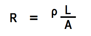
where
R = resistance of the wire grid in ohms
ρ = resistivity constant for the particular type of wire grid
L = length of wire grid
A = cross sectional area of wire grid
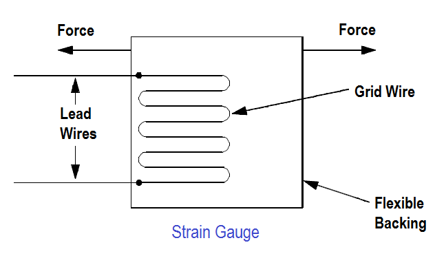 Figure 1 Strain Gauge
As the wire grid is distorted by elastic deformation, its length is increased, and its cross-sectional area decreases. These changes cause an increase in the resistance of the wire of the strain gauge. This change in resistance is used as the variable resistance in a bridge circuit that provides an electrical signal for indication of pressure. Figure 2 illustrates a strain gauge pressure transducer.
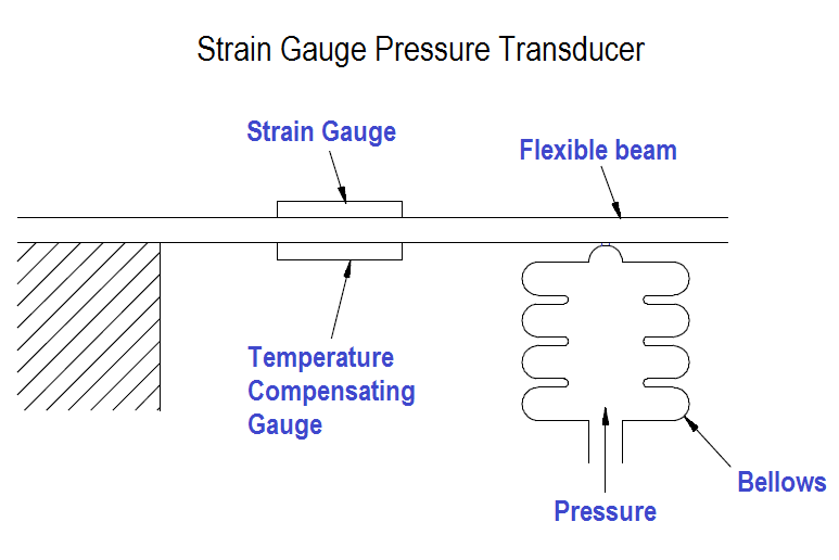
Figure 2 Strain Gauge Pressure Transducer
An increase in pressure at the inlet of the bellows causes the bellows to expand. The expansion of the bellows moves a flexible beam to which a strain gauge has been attached. The movement of the beam causes the resistance of the strain gauge to change. The temperature compensating gauge compensates for the heat produced by current flowing through the fine wire of the strain gauge. Strain gauges, which are nothing more than resistors, are used with bridge circuits as shown in Figure 3.
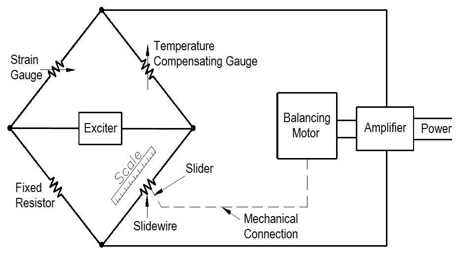
Figure 3 Strain Gauge Used in a Bridge Circuit
Note : The Balancing Motor Technique is a traditional method. Now a days many modern electronic circuits are available in place of motor.
Alternating current is provided by an exciter that is used in place of a battery to eliminate the need for a galvanometer. When a change in resistance in the strain gauge causes an unbalanced condition, an error signal enters the amplifier and actuates the balancing motor. The balancing motor moves the slider along the slidewire, restoring the bridge to a balanced condition. The slider’s position is noted on a scale marked in units of pressure.
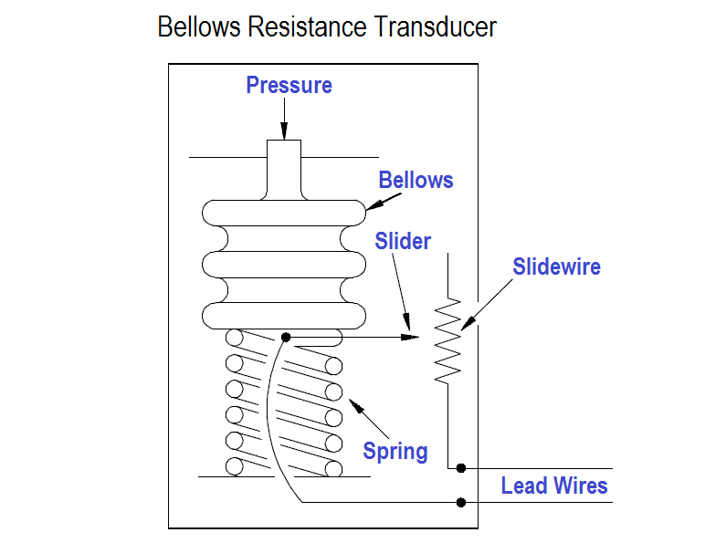
Figure 4 Bellows Resistance Transducer
Other resistance-type transducers combine a bellows or a bourdon tube with a variable resistor, as shown in Figure 4. As pressure changes, the bellows will either expand or contract. This expansion and contraction causes the attached slider to move along the slidewire, increasing or decreasing the resistance, and thereby indicating an increase or decrease in pressure.