Differential Pressure Transmitters Compensated Leg Systems
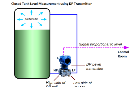
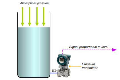
The simple and direct relationship between liquid height in a vessel and pressure at the bottom of that vessel is ruined if another source of pressure exists inside the vessel other than hydrostatic (elevation head). This is virtually guaranteed to be the case if the vessel in question is unvented. Any gas or vapor pressure accumulation in an enclosed vessel will add to the hydrostatic pressure at the bottom, causing any pressure-sensing instrument to falsely register a high level:
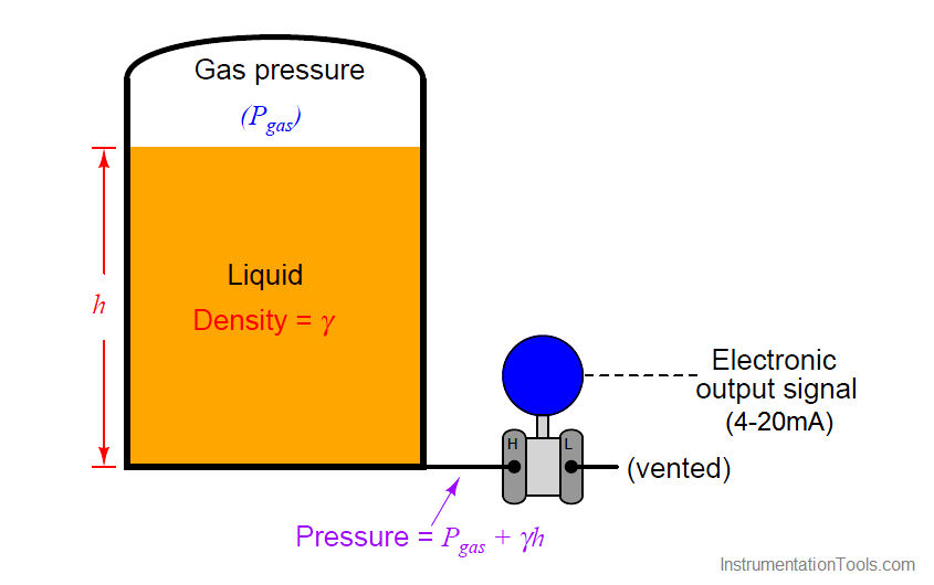
A pressure transmitter has no way of “knowing” how much of the sensed pressure is due to liquid elevation and how much of it is due to pressure existing in the vapor space above the liquid. Unless a way can be found to compensate for any non-hydrostatic pressure in the vessel, this extra pressure will be interpreted by the transmitter as additional liquid level.
Moreover, this error will change as gas pressure inside the vessel changes, so it cannot simply be “calibrated away” by a static zero shift within the instrument. The only way to hydrostatically measure liquid level inside an enclosed (non-vented) vessel is to continuously compensate for gas pressure.
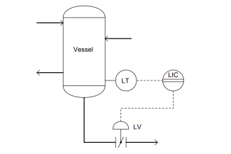
Fortunately, the capabilities of a differential pressure transmitter make this a simple task. All we need to do is connect a second impulse line (called a compensating leg), from the “Low” port of the transmitter to the top of the vessel, so the “Low” side of the transmitter experiences nothing but the gas pressure enclosed by the vessel, while the “High” side experiences the sum of gas and hydrostatic pressures. Since a differential pressure transmitter responds only to differences in pressure between “High” and “Low” sides, it will naturally subtract the gas pressure (Pgas) to yield a measurement based solely on hydrostatic pressure (γh):
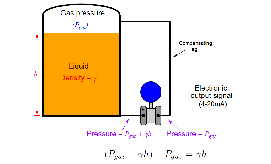
The amount of gas pressure inside the vessel now becomes completely irrelevant to the transmitter’s indication, because its effect is canceled at the differential pressure instrument’s sensing element. If gas pressure inside the vessel were to increase while liquid level remained constant, the pressure sensed at both ports of the differential pressure transmitter would increase by the exact same amount, with the pressure difference between the “high” and “low” ports remaining absolutely constant with the constant liquid level. This means the instrument’s output signal is a representation of hydrostatic pressure only, which represents liquid height (assuming a known liquid density γ).
Unfortunately, it is common for enclosed vessels to hold condensable vapors, which may over time fill a compensating leg full of liquid. If the tube connecting the “Low” side of a differential pressure transmitter fills completely with a liquid, this will add a hydrostatic pressure to that side of the transmitter, causing another calibration shift. This wet leg condition makes level measurement more complicated than a dry leg condition where the only pressure sensed by the transmitter’s “Low” side is gas pressure (Pgas):
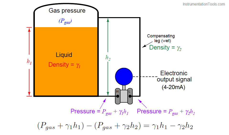
Gas pressure still cancels due to the differential nature of the pressure transmitter, but now the transmitter’s output indicates a difference of hydrostatic pressures between the vessel and the wet leg, rather than just the hydrostatic pressure of the vessel’s liquid level. Fortunately, the hydrostatic pressure generated by the wet leg will be constant, so long as the density of the condensed vapors filling that leg (γ2) is constant. If the wet leg’s hydrostatic pressure is constant, we can compensate for it by calibrating the transmitter with an intentional zero shift, so it indicates as though it were measuring hydrostatic pressure on a vented vessel.
Differential pressure = γ1h1 − Constant
We may ensure a constant density of wet leg liquid by intentionally filling that leg with a liquid known to be denser than the densest condensed vapor inside the vessel and non-miscible with the process fluid. We could also use a differential pressure transmitter with remote seals and capillary tubes filled with liquid of known density:
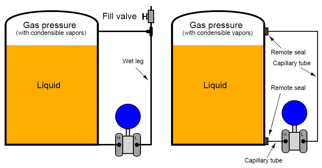
Remote seals are very useful in applications such as this, as the wet leg never requires re-filling.
An actual level transmitter installation using two remote seals (in this case, a Foxboro differential pressure transmitter) appears in this photograph:
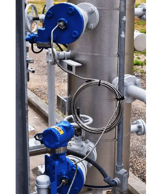
The vessel itself is insulated, and covered in sheet aluminum to protect the thermal insulation from impact and weather-related damage. White-painted flanged “nozzles” protrude from the vessel through the insulation to provide places for the level-sensing instrument to connect. You can see the two flanged remote seals (painted blue) where the armored (stainless steel) capillary tubes terminate. Note how the long capillary tube on the “wet” leg is neatly coiled to reduce the possibility of damage by snagging on any moving object.
Also Read : DP Transmitter Applications
An accessory commonly used with non-sealed (non-capillary) “wet leg” systems is a seal pot. This is a chamber at the top of the wet leg joining the wet leg line with the impulse line to the upper connection point on the process vessel. This “seal pot” maintains a small volume of liquid in it to allow for occasional liquid loss during transmitter maintenance procedures without greatly affecting the height of the liquid column in the wet leg:
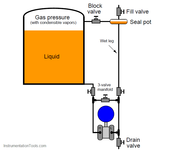
Regular operation of the transmitter’s three-valve manifold (and drain valve) during routine instrument maintenance inevitably releases some liquid volume from the wet leg. Without a seal pot, even a small loss of liquid in the wet leg may create a substantial loss in liquid column height within that tube, given the tube’s small diameter. With a seal pot, the (comparatively) large liquid volume held by the pot allows for some liquid loss through the transmitter’s manifold without substantially affecting the height of the liquid column within the wet leg.
Seal pots are standard on level measurement systems for boiler steam drums, where steam readily condenses in the upper impulse tube to naturally form a wet leg. Although steam will condense over time to refill the wet leg following a loss of water in that leg, the level measurements taken during that re-fill time will be in error. The presence of a seal pot practically eliminates this error as the steam condenses to replenish the water lost from the pot, since the amount of height change inside the pot due to a small volume loss is trivial compared to the height change in a wet leg lacking a seal pot.
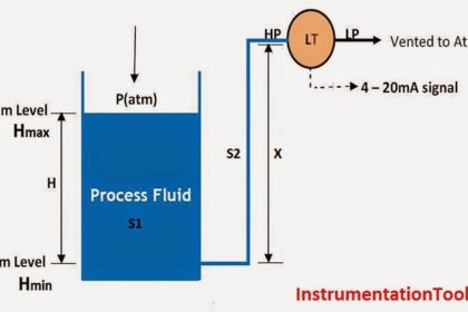
The following example shows the calibration table for a compensated-leg (wet) hydrostatic level measurement system, for a gasoline storage vessel and water as the wet leg fill fluid. Here, I am assuming a density of 41.0 lb/ft3 for gasoline and 62.4 lb/ft3 for water, with a 0 to 10 foot measurement range and an 11 foot wet leg height:
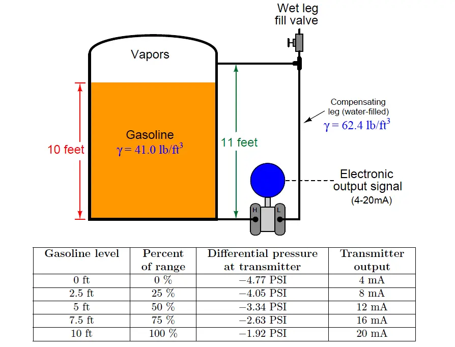
Note that due to the superior density and height of the wet (water) leg, the transmitter always sees a negative pressure (pressure on the “Low” side exceeds pressure on the “High” side).
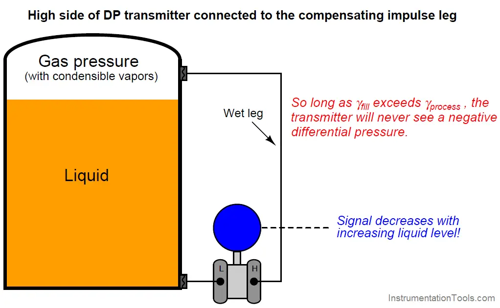
With some older differential pressure transmitter designs, this negative pressure was a problem. Consequently, it is common to see “wet leg” hydrostatic transmitters installed with the “Low” port connected to the bottom of the vessel and the “High” port connected to the compensating leg. In fact, it is still common to see modern differential pressure transmitters installed in this manner, although modern transmitters may be ranged for negative pressures just as easily as for positive pressures. It is vitally important to recognize that any differential pressure transmitter connected as such (for any reason) will respond in reverse fashion to increases in liquid level. That is to say, as the liquid level in the vessel rises, the transmitter’s output signal will decrease instead of increase:
Either way of connecting the transmitter to the vessel will suffice for measuring liquid level, so long as the instrumentation receiving the transmitter’s signal is properly configured to interpret the signal. The choice of which way to connect the transmitter to the vessel should be driven by fail-safe system design, which means to design the measurement system such that the most probable system failures – including broken signal wires – result in the control system “seeing” the most dangerous process condition and therefore taking the safest action.
Also Read : Differential Pressure Transmitter Working Principle
Credits : Tony R. Kuphaldt – Creative Commons Attribution 4.0 License


Hi, thanks for this article. However I would like to point to your attention that pressures related to height “h” are expressed as( ygh) not as you keep repeating (yh), “g” being the earth gravity, “y” density and h the height of the liquid. So please do correct. thank you.