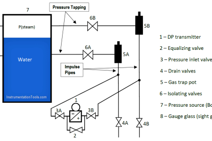
The combination of two differential pressure ports makes the DP transmitter very versatile as a pressure-measuring device. This one instrument may be used to measure pressure differences, positive (gauge) pressures, negative (vacuum) pressures, and even absolute pressures, just by connecting the “high” and “low” sensing ports differently.
In every DP transmitter application, there must be some means of connecting the transmitter’s pressure-sensing ports to the points in a process. Metal or plastic tubes (or pipes) work well for this purpose, and are commonly called impulse lines, or gauge lines, or sensing lines. This is equivalent to the test wires used to connect a voltmeter to points in a circuit for measuring voltage.
Typically, these tubes are connected to the transmitter and to the process by means of compression fittings which allow for relatively easy disconnection and reconnection of tubes.
Measuring Process Vessel Clogging
We may use the DP transmitter to measure an actual difference of pressure across a process vessel such as a filter, a heat exchanger, or a chemical reactor.
The following illustration shows how a differential pressure transmitter may be used to measure clogging of a water filter:
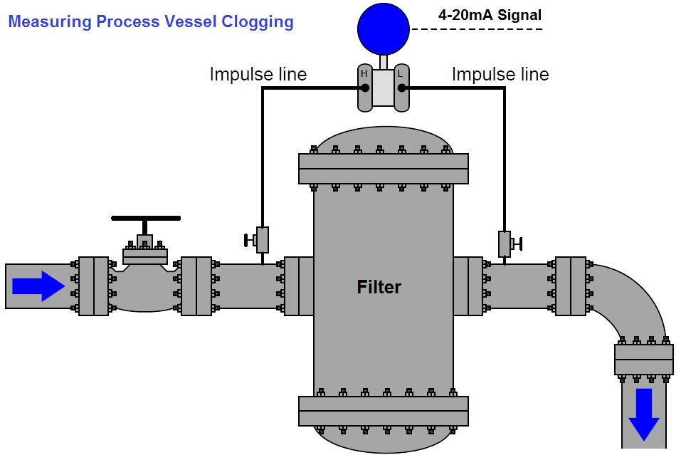
Note how the high side of the DP transmitter connects to the upstream side of the filter, and the low side of the transmitter to the downstream side of the filter. This way, increased filter clogging will result in an increased transmitter output. Since the transmitter’s internal pressure sensing diaphragm only responds to differences in pressure between the “high” and “low” ports, the pressure in the filter and pipe relative to the atmosphere is completely irrelevant to the transmitter’s output signal.
The filter could be operating at a line pressure of 10 PSI or 10000 PSI – the only variable the DP transmitter measures is the pressure drop across the filter. If the upstream side is at 10 PSI and the downstream side is at 9 PSI, the differential pressure will be 1 PSI (sometimes labeled as PSID, “D” for differential ). If the upstream pressure is 10000 PSI and the downstream pressure is 9999 PSI, the DP transmitter will still see a differential pressure of just 1 PSID.
Likewise, the technician calibrating the DP transmitter on the workbench could use a precise air pressure of just 1 PSI (applied to the “high” port, with the “low” port vented to atmosphere) to simulate either of these real-world conditions. The DP transmitter simply cannot tell the difference between these three scenarios, nor should it be able to tell the difference if its purpose is to exclusively measure differential pressure.
Measuring Positive Gauge Pressure
DP instruments may also serve as simple gauge pressure instruments if needed, responding to pressures in excess of atmosphere. If we simply connect the “high” side of a DP instrument to a process vessel using an impulse tube, while leaving the “low” side vented to atmosphere, the instrument will interpret any positive pressure in the vessel as a positive difference between the vessel and atmosphere:
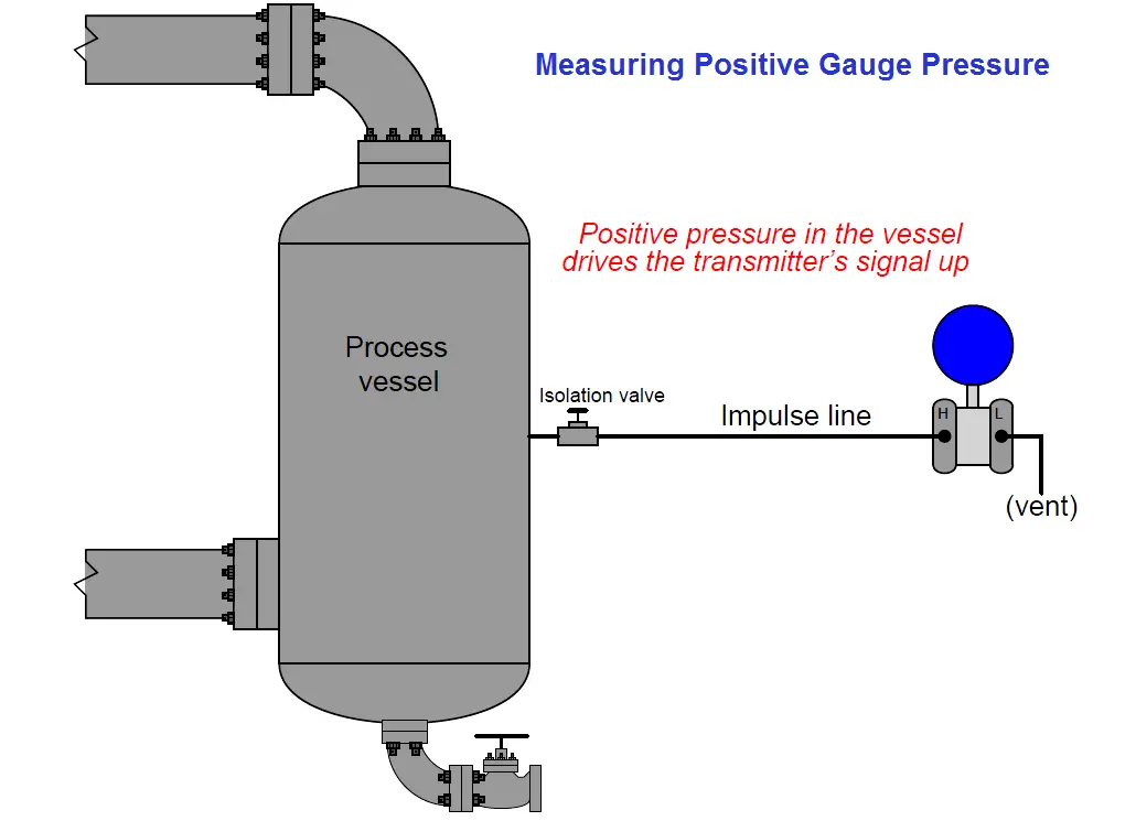
Although this may seem like a waste of the transmitter’s abilities (why not just use a simpler gauge pressure transmitter with just one port?), it is actually a very common application for DP transmitters. This usage of a differential device may not actually be a “waste” if true-differential applications exist at the same facility for that pressure transmitter, which means only one spare transmitter need be stocked in the facility’s warehouse instead of two spare transmitters (one of each type).
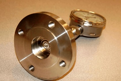
Most DP instrument manufacturers offer “gauge pressure” versions of their differential instruments, with the “high” side port open for connection to an impulse line and the “low” side of the sensing element capped off with a special vented flange, effectively performing the same function we see in the above example at a slightly lesser cost.
A close-up photograph of a Rosemount model 1151GP gauge pressure transmitter shows the port-less flange on the “low” side of the pressure sensing module. Only the “high” side of the sensor has a place for an impulse line to connect:
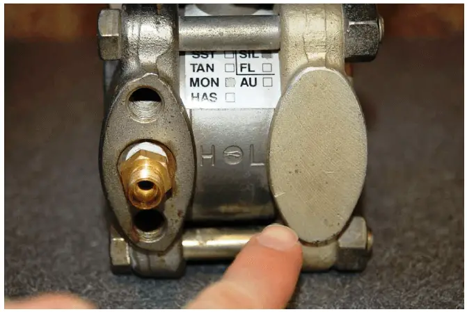
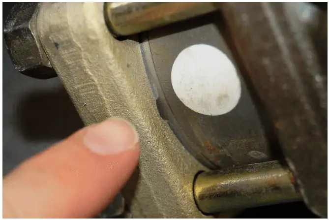
A closer look at this flange reveals a vent near the bottom, ensuring the “low” side of the pressure-sensing capsule always senses ambient (atmospheric) pressure:
Measuring Absolute Pressure
Absolute pressure is defined as the difference between a given fluid pressure and a perfect vacuum, as opposed to gauge pressure which is the difference between a fluid’s pressure and the atmospheric air pressure.
We may build an absolute pressure sensing instrument by taking a DP instrument and sealing the “low” side of its pressure-sensing element in connection to a vacuum chamber. This way, any pressure greater than a perfect vacuum will register as a positive difference:
Most absolute pressure transmitters resemble “gauge pressure” adaptations of DP transmitters, with only one port available to connect an impulse line. Unlike gauge pressure transmitters, though, absolute pressure transmitters do not have vent holes on their “low” sides. The “low” side of an absolute pressure transmitter must be a sealed vacuum in order to accurately measure the “high” side fluid pressure in absolute terms.
Absolute pressure measurement is important for a variety of process applications, including boiling-point control and mass flow measurement of gases. The boiling temperature of any liquid is a function of the absolute pressure it experiences, and in applications where boiling temperature must be precisely controlled in order to achieve a certain outcome (e.g. vacuum distillation of crude oil, for example) the best type of pressure measurement to use absolute. When computing the mass flow rate of gases in a pipe, the relationship between volume and molecular count is a function of both temperature and pressure (both absolute), and so absolute pressure measurement is indispensable here as well.
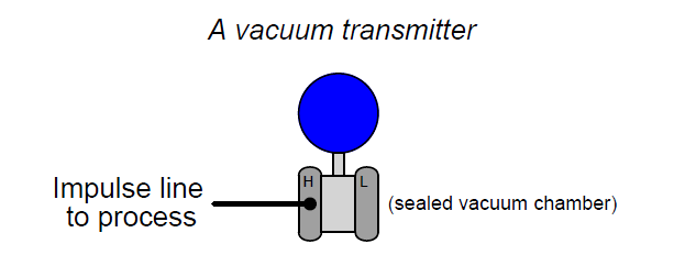
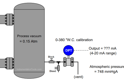
Measuring vacuum
The same principle of connecting one port of a DP device to a process and venting the other works well as a means of measuring vacuum (pressures below that of atmosphere). All we need to do is connect the “low” side to the vacuum process and vent the “high” side to atmosphere:
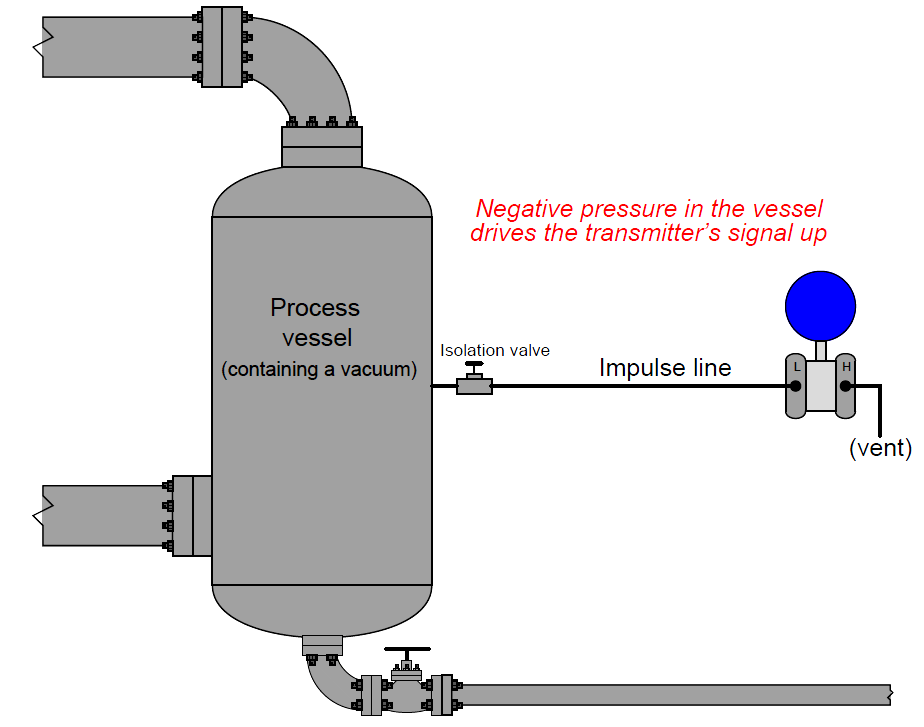
Any pressure in the process vessel less than atmospheric will register to the DP transmitter as a positive difference (with Phigh greater than Plow). Thus, the stronger the vacuum in the process vessel, the greater the signal output by the transmitter.
This last statement deserves some qualification. It used to be, the way analog pneumatic and electronic transmitters were designed many years ago, that the only way to obtain an increasing signal from a DP instrument was to ensure the “high” port pressure rose in relation to the “low” port pressure (or conversely stated, to ensure the “low” port pressure dropped in relation to the “high” side pressure).
However, with the advent of digital electronic technology, it became rather easy to program a DP instrument with a negative range, for example 0 to −10 PSI. This way, a decreasing pressure as interpreted by the transmitter would yield an increasing output signal.
It is rare to find a pressure transmitter calibrated in such a way, but bear in mind that it is possible. This opens the possibility of using a regular “gauge” pressure transmitter (where the “high” port connects to the process vessel and the “low” port is always vented to atmosphere by virtue of a special flange on the instrument) as a vacuum instrument. If a gauge pressure transmitter is given a negative calibration span, any decreasing pressure seen at the “high” port will yield an increasing output signal.
Credits : Tony R. Kuphaldt – Creative Commons Attribution 4.0 License


Sir, please describe that how air DP filter transmitter works ,means according to 4-20ma,
At what reading compressor will trip. What should be the range of tx,