Inst ToolsInst ToolsInst Tools
  • Courses
  • Automation
    • PLC
    • Control System
    • Safety System
    • Communication
    • Fire & Gas System
  • Instrumentation
    • Design
    • Pressure
    • Temperature
    • Flow
    • Level
    • Vibration
    • Analyzer
    • Control Valve
    • Switch
    • Calibration
    • Erection & Commissioning
  • Interview
    • Instrumentation
    • Electrical
    • Electronics
    • Practical
  • Q&A
    • Instrumentation
    • Control System
    • Electrical
    • Electronics
    • Analog Electronics
    • Digital Electronics
    • Power Electronics
    • Microprocessor
  • Request
Search
  • Books
  • Software
  • Projects
  • Process
  • Tools
  • Basics
  • Formula
  • Power Plant
  • Root Cause Analysis
  • Electrical Basics
  • Animation
  • Standards
  • 4-20 mA Course
  • Siemens PLC Course
Reading: Conductive Level Switch Principle
Share
Font ResizerAa
Inst ToolsInst Tools
Font ResizerAa
  • Courses
  • Design
  • PLC
  • Interview
  • Control System
Search
  • Courses
  • Automation
    • PLC
    • Control System
    • Safety System
    • Communication
    • Fire & Gas System
  • Instrumentation
    • Design
    • Pressure
    • Temperature
    • Flow
    • Level
    • Vibration
    • Analyzer
    • Control Valve
    • Switch
    • Calibration
    • Erection & Commissioning
  • Interview
    • Instrumentation
    • Electrical
    • Electronics
    • Practical
  • Q&A
    • Instrumentation
    • Control System
    • Electrical
    • Electronics
    • Analog Electronics
    • Digital Electronics
    • Power Electronics
    • Microprocessor
  • Request
Follow US
All rights reserved. Reproduction in whole or in part without written permission is prohibited.
Inst Tools > Blog > Level Measurement > Conductive Level Switch Principle

Conductive Level Switch Principle

Last updated: April 24, 2019 2:55 pm
Editorial Staff
Level Measurement Switches
No Comments
Share
3 Min Read
SHARE

Perhaps the simplest (and oldest) form of electrical level detection is where a pair of metal electrodes contacts the process material to form a complete electrical circuit, actuating a relay.

This type of switch, of course, only works with granular solids and liquids that are electrically conductive (e.g. potable or dirty water, acids, caustics, food liquids, coal, metal powders) and not with nonconducting materials (e.g. ultra-pure water, oils, ceramic powders).

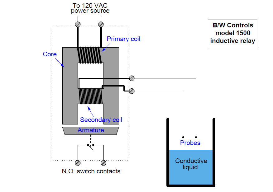
A legacy design for conductive level switches is the model 1500 “induction relay” originally manufactured by B/W Controls, using a special transformer/relay to generate an isolated AC probe voltage and sense the presence of liquid:

Conductive Level Switch
Conductive Level Switch Principle

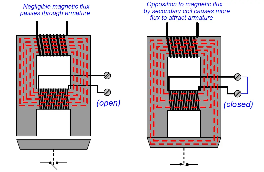
Line voltage (120 VAC) energizes the primary coil, sending a magnetic field through the laminated ferrous core of the relay. This magnetic field easily passes through the center of the secondary coil when the secondary circuit is open (no liquid closing the probe circuit), thus completing the magnetic “circuit” in the core. With the magnetic circuit thus completed, the armature will not be attracted to the core.

However, when a circuit is completed by liquid level rising to contact both probes, the secondary coil’s resulting current “bucks” the magnetic flux through its center, causing more magnetic flux to bypass to the end poles where it attracts the ferrous armature toward the core frame. This physical attraction actuates switch contacts which then signal the presence of liquid level at the probes.

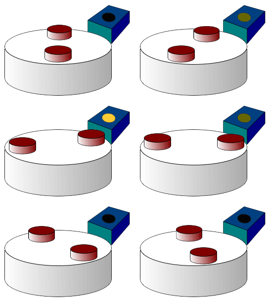
The following pair of illustrations shows the two conditions of this level switch, with the magnetic lines of flux highlighted as dashed lines through the core:
Conductive Level Switch Working

The “transformer” design of this particular conductive level switch not only provides electrical isolation between the probes and the energizing (120 VAC) circuit, but it also enables a wide range of detection voltages to be generated for the probes just by altering the number of wire “turns” in the secondary coil.

The B/W Controls model 1500 inductive relay is available in a variety of AC voltage output levels, ranging from 12 VAC (for detecting metallic substances) to 800 VAC for use with demineralized water such as that found in steam boiler systems.

Note : This is a old Model Design

More modern variations on the same design theme use much lower AC voltages to energize the probes, employing sensitive semiconductor amplifier circuits to detect probe current and signal liquid level.
Articles You May Like :

What is LVDT ?

Optical Level Switch

Area Velocity Flow Meter

Paddle Switch Principle

Safety Switches Operations

Don't Miss Our Updates
Be the first to get exclusive content straight to your email.
We promise not to spam you. You can unsubscribe at any time.
Invalid email address
You've successfully subscribed !

Continue Reading

Purpose of Tank Gauging Level Measurement
Open Tank Interface Level Measurement
What is a Level Switch? Types of Level Switches
Microwave Barrier Level Switch Working Principle
How to Calculate mmWC Range of Level Transmitter with Examples?
Safety Switches for Controlling Conveyor Operations
Share This Article
Facebook Whatsapp Whatsapp LinkedIn Copy Link
Share
Leave a Comment

Leave a Reply Cancel reply

Your email address will not be published. Required fields are marked *

Stay Connected

128.3kFollowersLike
69.1kFollowersFollow
210kSubscribersSubscribe
38kFollowersFollow

Categories

Explore More

Magnetic Float Level Switch Working Animation
Basics of Hydrostatic Level Measurement
What is Thermal Differential Level Measurement?
Float & Dial Level Gauge Principle
DP Transmitter with Two Seals applications
What is a Limit Switch ?
Effect of Tank Design on Accuracy of Level Measurement
Level Measurement Objective Questions

Keep Learning

Hydrostatic Level Measurement

Hydrostatic Level Measurement

Belt Sway Switch Principle

Belt Sway Switch Working Principle

Wet Leg Level Transmitter

Basics of DP Level Measurement

Installation and Calibration of Level Transmitter

Installation and Calibration of Level Transmitter

RF-Capacitance Level Switch Principle

RF Capacitance Level Switch Working Principle

Mechanical Vibration Switch

Vibration Switch Working Principle

Radar and Ultrasonic Level Transmitter Problems Troubleshooting

Radar and Ultrasonic Level Transmitter Practical Problems Troubleshooting

hall-effect-sensor

Hall Effect Sensor Working Principle Animation

Learn More

transmitter calibration procedure

Transmitter Calibration Procedure

PLC Logic Example on Multiple Switches and Motors

PLC Logic Example on Multiple Switches and Motors

pressure transmitter calibration setup

Questions on Pressure Transmitter Calibration Setup

Fiber Optic Patch Cord

What is a Fiber Optic Patch Cord? – Types, Explained

Electrical Drives and Controls Interview Questions

Electrical Drives and Controls Interview Questions

Questions on Single Loop Controller

Single Loop Controller Questions

Smart HART Transmitter

Analysis of HART communicator and Smart HART Transmitter

surface-mounted water pump

Surface-mounted Water Pump

Menu

  • About
  • Privacy Policy
  • Copyright

Quick Links

  • Learn PLC
  • Helping Hand
  • Part Time Job

YouTube Subscribe

Follow US
All rights reserved. Reproduction in whole or in part without written permission is prohibited.
Welcome Back!

Sign in to your account

Username or Email Address
Password

Lost your password?