Inst ToolsInst ToolsInst Tools
  • Courses
  • Automation
    • PLC
    • Control System
    • Safety System
    • Communication
    • Fire & Gas System
  • Instrumentation
    • Design
    • Pressure
    • Temperature
    • Flow
    • Level
    • Vibration
    • Analyzer
    • Control Valve
    • Switch
    • Calibration
    • Erection & Commissioning
  • Interview
    • Instrumentation
    • Electrical
    • Electronics
    • Practical
  • Q&A
    • Instrumentation
    • Control System
    • Electrical
    • Electronics
    • Analog Electronics
    • Digital Electronics
    • Power Electronics
    • Microprocessor
  • Request
Search
  • Books
  • Software
  • Projects
  • Process
  • Tools
  • Basics
  • Formula
  • Power Plant
  • Root Cause Analysis
  • Electrical Basics
  • Animation
  • Standards
  • 4-20 mA Course
  • Siemens PLC Course
Reading: Non-Contacting Radar Level Transmitter Working Principle
Share
Notification Show More
Font ResizerAa
Inst ToolsInst Tools
Font ResizerAa
  • Courses
  • Design
  • PLC
  • Interview
  • Control System
Search
  • Courses
  • Automation
    • PLC
    • Control System
    • Safety System
    • Communication
    • Fire & Gas System
  • Instrumentation
    • Design
    • Pressure
    • Temperature
    • Flow
    • Level
    • Vibration
    • Analyzer
    • Control Valve
    • Switch
    • Calibration
    • Erection & Commissioning
  • Interview
    • Instrumentation
    • Electrical
    • Electronics
    • Practical
  • Q&A
    • Instrumentation
    • Control System
    • Electrical
    • Electronics
    • Analog Electronics
    • Digital Electronics
    • Power Electronics
    • Microprocessor
  • Request
Follow US
All rights reserved. Reproduction in whole or in part without written permission is prohibited.
Inst Tools > Blog > How It Works > Non-Contacting Radar Level Transmitter Working Principle

Non-Contacting Radar Level Transmitter Working Principle

Last updated: September 14, 2016 6:15 pm
Editorial Staff
How It Works Level Measurement
3 Comments
Share
5 Min Read
SHARE

For non-contacting radar level measurement there are two main modulation techniques,

  1. Pulse radar technique
  2. FMCW (Frequency Modulated Continuous Wave) radar technique

Basic principle

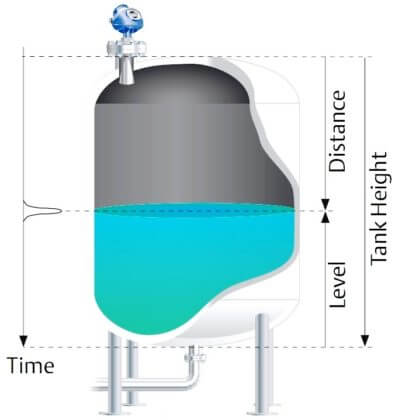
Non-contacting pulse radar sends out a microwave signal that bounces off the product surface and returns to the sensor. The transmitter measures the time delay between the transmitted and received echo signal and the on-board microprocessor calculates the distance to the liquid surface using the formula:

Distance = (Speed of light x time delay) / 2

Once the transmitter is programmed with the tank reference height of the application – usually the bottom of the tank or chamber – the liquid level is calculated by the microprocessor.

Level = Tank Height – Distance

radar-level-sensor-
radar-level-sensor-

The FMCW radar also transmits microwaves towards the product surface, but the transmitted signal is of continuously varying frequency. When the signal has travelled down to the liquid surface and back to the antenna, it is mixed with the signal that is being transmitted at that time. The difference in frequency between the received and transmitted signal is directly proportional to the distance to the liquid with high precision.

Because it is non-contacting, the Sensor’s susceptibility to corrosion is limited and it is an ideal choice for viscous, sticky, and abrasive fluids.

Non-contacting radar can frequently be used in vessels with agitators. High frequency devices can be completely isolated from the process with PTFE seals and can be used with valves.

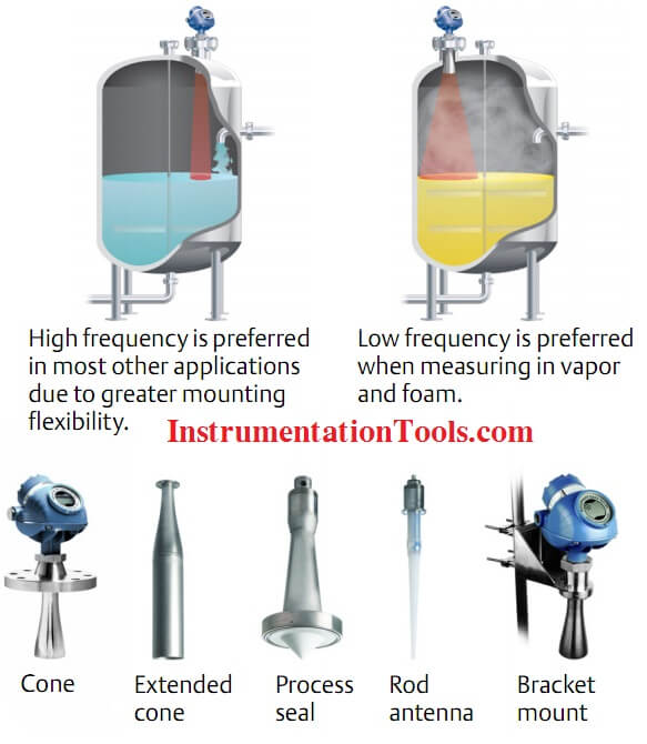
The frequency of the non-contacting radar can impact its performance. A lower frequency reduces sensitivity to vapor, foam, and contamination of the antenna, whereas a higher frequency keeps the radar beam narrow in order to minimize influence from nozzles, walls, and disturbing objects. Beam width is inversely proportional to antenna size. The beam width of a given frequency will decrease as the antenna size increases.

Advantages

  1. Non-contacting radar provides a top-down, direct measurement as it measures the distance to the surface.
  2. It can be used with liquids, sludges, slurries, and some solids.
  3. A key advantage of radar is that no compensation is necessary for changes in density, dielectric, or conductivity of the fluid.
  4. Changes in pressure, temperature, and most vapor space conditions have no impact on the accuracy of radar measurements.
  5. In addition, radar devices have no moving parts
  6. so maintenance is minimal.
  7. Non- contacting radar devices can be isolated from the process by using barriers such as PTFE seals or valves.
  8. Since it is not in contact with the measured media it is also good for corrosive and dirty application.

Limitations

  1. For non-contacting radar, good installation is the key to success. The sensor needs a clear view of the surface with a smooth, unobstructed, unrestricted mounting nozzle.
  2. Obstructions in the tank, such as pipes, strengthening bars and agitators can cause false echoes, but most transmitters have sophisticated software algorithms to allow masking or ignoring of these echoes.
  3. Non-contacting radar can handle agitation, but their success will depend on a combination of the fluid properties and the amount of turbulence. Dielectric constant (DK) of the medium and the surface conditions will impact the measurement. The measurement may be influenced by the presence of foam. Energy tends to not be reflected by light and airy foam while a dense and heavy foam typically reflects the energy.
  4. With low dielectric process fluids, much of the radiated energy is lost to the fluid, leaving very little energy to be reflected back to the sensor. Water and most chemical solutions have a high DK; fuel oil, lube oil and some solids, such as lime, have a low DK.
  5. If the surface is turbulent, whether from agitation, product blending, or splashing, more of the signal is lost. So a combination of a low dielectric fluid and turbulence can limit the return signal to a non- contacting radar. To get around this, bypass pipes or stilling wells can be used to isolate the surface from the turbulence.

Types of Radar Level Transmitter Antennas

Types of Radar Level Transmitter Antennas
Don't Miss Our Updates
Be the first to get exclusive content straight to your email.
We promise not to spam you. You can unsubscribe at any time.
Invalid email address
You've successfully subscribed !

Continue Reading

Dead Weight Tester Working Animation
Types of Industrial Level Sensors
Pressure Transmitters Leg Compensation Technique
Open Tank DP Level Transmitter Calculations
Differential Pressure Switch Working Principle
DP Transmitter Interface Level Measurement Principle, Limitations, Selection, Installation, Design & Calibration
Share This Article
Facebook Whatsapp Whatsapp LinkedIn Copy Link
Share
3 Comments
  • mohammad says:
    February 25, 2016 at 4:45 pm

    thank u!

    Reply
  • Abdul Qayyoum says:
    March 1, 2021 at 12:59 am

    Instrument technician full courses

    Reply
  • Gustavo Delgado says:
    March 2, 2021 at 7:39 pm

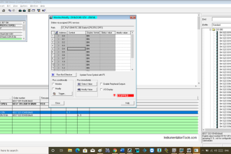
    The radar levels TX have some problems when measure oil or lube, due the the low DK of the liquid, and when the level liquid is low, on those cases the Echo profile will show two peaks, one weak, which is the reflect of the liquid, and one more strong, which is from the floor, but because a delay of the back signal the measure is higher than really should be, some devices come with a software which suppresses or cut the strong back of the signal in low measuring levels. The guide wave radars have better performance and are capable to measuring liquid phases, but are a little expensive.

    Reply

Leave a Reply Cancel reply

Your email address will not be published. Required fields are marked *

Stay Connected

128.3kFollowersLike
69.1kFollowersFollow
210kSubscribersSubscribe
38kFollowersFollow

Categories

Explore More

Capacitance Level Transmitter Animation
Float Level Switch Working Principle
Closed tank DP Level Transmitter with wet leg elevation zero direct mount Calibration
How to Find LRV and URV of Closed Tank DP Level Transmitter
Remote Seal Differential Pressure Transmitters Principle
Effect of Temperature & Pressure on Level Measurement
How can we use a DP Flow Transmitter for Level Measurement
Tilt Level Switch Working Principle

Keep Learning

Types of Tank Gauging Level Measurement Systems

Types of Tank Gauging Level Measurement Systems

Displacer Level Sensor Working Animation

Displacer Level Sensor Working Animation

Level Transmitter with Zero Suppression

DP Level Transmitters Compensation Techniques

Tilt Level Switch Working Animation

Alternative Vessel Level Indication

What is the Simple Alternative Vessel Level Indication?

guided-wave radar Transmitter Setup

Guided-Wave Radar Instruments Diagnostics

Pressure Transmitter

Pressure Transmitter Animation

Ultrasonic Level Switch Principle

Ultrasonic Level Switch Principle

Learn More

InTouch SCADA Password Protection

InTouch SCADA Login Password Security

Redundant Power Supply WITH Diode Unit

Redundant Power Supply for Critical Field Panels

Burning Oven PLC Program

PLC Program for Ceramic Burning Oven Conveyor System

RTD Calculator Software

RTD Calculator Software

Parallel Circuit Parallel Current Calculations

Parallel Circuit Current Calculations

Solar Arrays

Solar Photovoltaic Cells – Parts of the Solar Panel

What we need to Know before Tune a PID Controller

What we need to Know before Tune a PID Controller ?

Classification of Flow Measurement Techniques

Classification of Flow Measurement Techniques

Menu

  • About
  • Privacy Policy
  • Copyright

Quick Links

  • Learn PLC
  • Helping Hand
  • Part Time Job

YouTube Subscribe

Follow US
All rights reserved. Reproduction in whole or in part without written permission is prohibited.
Welcome Back!

Sign in to your account

Username or Email Address
Password

Lost your password?