One of the most common questions is regarding the difference between DCS and PLC as well as between PLC and SCADA – and if there is any difference at all between them.
Both the DCS and PLC were invented in the mid nineteen seventies. Because there are many brands of DCS, PLC, and RTU, only broad generalizations are possible.
DCS is focused on process control with analog signals, used as the main control system in process industries like refining, petrochemicals, and chemicals etc.
PLC is focused on discrete automation with discrete on-off signals, used on factory assembly lines and bottling lines etc. PLC and DCS are both constantly evolving.
Difference between DCS, PLC and RTU
Today DCS support discrete I/O and some logic functions and PLCs support analog I/O and some control functions. There are many similarities between DCS and PLC so sometimes this debate can get confusing.
However, there also are differences between them. As a result, each has carved out industry niches where they are used.
Some plants use both DCS and PLC. For instance, in a refinery a PLC may be used on a package unit integrated with the main plant-wide DCS.
Hardware and Software
PLC today have features in the past only found in a DCS. However, this doesn’t necessarily mean PLC and DCS features are now the same because DCS is also constantly evolving new features.
The type of fieldbus used and how tightly it is integrated in the control system using EDDL files and with the IDM software is one of the main differences between PLC and DCS.
Distributed Control System – DCS

DCS supports redundancy for controllers, power supply, and control network, as well as redundant I/O cards including fieldbus interface cards in the same backplane.
The control network supports peer-to-peer communication between controllers. The control network is typically a proprietary application protocol over Ethernet media and IP.
In a DCS the field cabling lands on a Field Terminal Assembly (FTA) where a special system cable with connector takes the signals to the I/O card.
Loops in a DCS are executed individually. The scan time in a DCS is set individually for each loop. Most loops run at 1000 ms although 250 ms is common for pressure and flow loops in refining and petrochemicals, and as fast as 100 ms is possible.
Most importantly, the scan time is isochronous as required for PID control and time-based functions such as integration/totalizing and lead-lag dynamic compensation etc., meaning it is constant, not changing with task loading.
Loops in a DCS are also managed individually. Addition, change, and download to one loop do not affect other loops.
A DCS has an integrated development environment where I/O, control strategy, and operator graphics are created together and stored in a single database.
This means that once a tag is created in the DCS it automatically becomes available everywhere in the system with the same human readable tag name for use in basic control, advanced control, graphics, faceplates, trending, alarming, and tuning etc. without mapping data through registers or other tag names. This makes additions and changes easy.
The sensor & actuator level “H1” fieldbus network supported by DCS is primarily FOUNDATION fieldbus for instrumentation and PROFIBUS-DP for motor controls.
The DCS comes with its own native fieldbus interface cards. The engineering software therefore automatically configures the communication interface cards for the variables used in the control strategy and graphics etc.
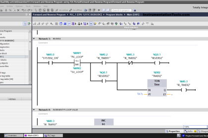
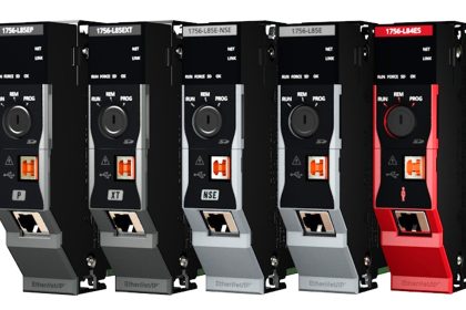
Programmable Logic Controller – PLC
PLC comes in many sizes; meaning various I/O and program capacities. Their capabilities vary greatly making generalizations difficult.
The smallest sizes are typically referred to as nano PLC, micro PLC, and mini PLC having fixed I/O and are used in small stand-alone applications.
These are not discussed further in this white paper as they generally do not support “pass-through” of digital communication with intelligent devices.
This article looks at the larger PLCs with flexible I/O-subsystem in a backplane that work as part of a larger system.

Large PLC support redundancy for CPU, power supply, and possibly the control network, but typically not for I/O cards although there are large PLC that support I/O redundancy by using duplicate I/O-subsystems with separate backplanes where the field instruments are wired in parallel to both I/O subsystems.
The control network is typically a standard industrial Ethernet application protocol over Ethernet media and IP. For PLC the field cabling lands directly on the I/O card.
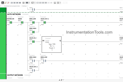
PLC supports very fast scan times as required in discrete manufacturing, especially for discrete logic.
However, it should be noted that PID loops add to the CPU load much more than discrete logic thus making the scan time slower. The scan time, although fast, may vary with task loading.
Loops are not handled individually in a PLC. Addition or change to loop requires a download of the entire program which affects other loops in the CPU as well.
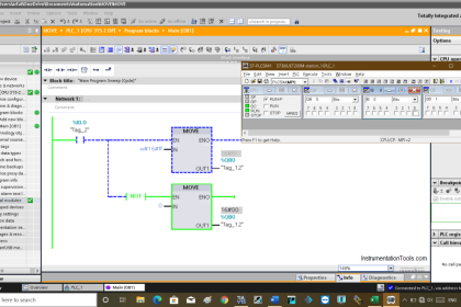
The PLC configuration software is separate from the HMI software as they generally come from different manufacturers. That is, two separate databases.
The logic programming is first done in the PLC configuration software. Next the OPC server has to be configured.
For a native OPC server this happens automatically, but for a third-party OPC server manual data mapping is required which is time consuming and error prone requiring thorough testing.
Therefore native OPC server is preferred. Lastly the HMI database has to be configured for graphics, alarms, and trend etc.
If the HMI software comes from the same manufacturer as the PLC, the intermediate data mapping step may not be required, making the integration easier.
However, even if the PLC and HMI manufacturer are the same, the data mapping may still be required in case the two products were designed separately.
The sensor & actuator level “H1” fieldbus network supported by PLC is primarily ASI, CompoNet, IO-link, and PROFIBUS-PA for instrumentation and PROFIBUS-DP or DeviceNet for motor controls.
Each PLC manufacturer typically has a native protocol, yet open standard, which the PLC architecture is built around. It may be PROFIBUS, DeviceNet, Modbus, or CC-link etc.
The PLC comes with its own native interface cards for the native protocol supported by the PLC manufacturer, but relies on third-party interface cards for other fieldbus protocols.
The engineering software therefore automatically configures the communication interface card for the native protocol.
However, for other fieldbus protocols the interface card must be configured using separate to map the variables before they can be used in the control strategy and graphics etc.
Remote Terminal Unit – RTU
RTUs are designed for use in applications in remote locations unattended where no power is available. This may include freshwater reservoirs, onshore oil & gas well pads, as well as unmanned offshore platforms.
")
RTUs therefore have extremely low power consumption, much lower than DCS and PLC, to enable operation on solar power and batteries.
These applications are typically referred to as Supervisory Control and Data Acquisition (SCADA) or telemetry meaning supervision from a far away central location.
The SCADA software sits in the central office connected over a backhaul network typically using radio communication to far away and often widely geographically spread out RTUs. The communication may be interrupted for long periods of time.
RTUs therefore have onboard data storage continuing local data collection for more than a month if backhaul communication is lost as well as “history backfill” uploading this data once the connection is reestablished.
Report by exception communication mechanisms are often used to minimize backhaul communication since pay per data volume long distance Wide Area Networks (WAN) like mobile (cellular), microwave, and satellite are often used in the remote applications served. Flow computing capability according to AGA is typically built-in.
The RTU configuration software is separate from the HMI software from a third-party manufacturer. That is, two separate databases. First the RTU is configured; next the OPC server is configured.
For a native OPC server this happens automatically, but for a third-party OPC server manual data mapping is required which is time consuming and error prone requiring thorough testing.
Therefore native OPC server is preferred. Lastly the HMI database has to be configured for graphics, alarms, and trend etc. The terms HMI software and SCADA software are used interchangeably.
The 4-20 mA AI and AO cards for a RTU optionally support native HART “pass-through”. Thus separate HART multiplexer (MUX) hardware and associated integration work is not required.
Native HART pass-through AI and AO cards are much easier to integrate and should be specified if 4-20 mA is used.
Because RTUs are generally used in very slow monitoring applications not requiring fast control, some applications do not use the real-time analog 4-20 mA, just the digital HART communication multi-drop topology.
This means the field instruments draw less than 4 mA instead of up to 20 mA, thus further reducing overall power consumption.
Article Source: eddl.org
PLC Tutorials :
What is Programmable Logic Controller ?
What is Ladder Diagram Programming ?
History of Programmable Logic Controllers
Mis-conceptions of PLC Ladder Logic
Contacts and coils in PLC
Digital Input and Output Modules
Analog I/O and Network I/O
PLC Input/Output Modules
Memory Mapping in PLC
Analog Input Scaling
PLC Example with Switches
Counter Instructions
Timer Instructions
Math instructions
Data Instructions
Ladder Logic Questions
If you liked this article, then please subscribe to our YouTube Channel for PLC and SCADA video tutorials.
You can also follow us on Facebook and Twitter to receive daily updates.


i need full information about instrument dcs and plc
Thanks for your share this good knowledge
Good moorning Thak you for your help ,we find important things in your articles,many knowledges and informations ,how to do to have this articles and new articles in my email box .
best regards
Hi, Check “Subscribe” option available on Top Black color Menu.
Good morning and thankfully for your help,I’m find useful things in your article’s,many knowledge and informations..
Thank you very much fo your sincere efforts.
Here i have a question about a word I have found hard to comprehend, which is ‘isochronous “?
i think there is something wrong to this.’Today DCS support discrete I/O and some logic functions and PLCs support analog I/O and some control functions.
Just found this article. It’s delusional and written by someone who doesn’t know what they’re talking about or has never worked on anything but their one specific DCS. There’s a reason why Rockwell has 95% of all industry and Honeywell has less than 1% (in the US). The line between SCADA and DCS doesn’t exist anymore and everything that is praised about DCS is out of date.
such a great and elaborate explanation