Inst ToolsInst ToolsInst Tools
  • Courses
  • Automation
    • PLC
    • Control System
    • Safety System
    • Communication
    • Fire & Gas System
  • Instrumentation
    • Design
    • Pressure
    • Temperature
    • Flow
    • Level
    • Vibration
    • Analyzer
    • Control Valve
    • Switch
    • Calibration
    • Erection & Commissioning
  • Interview
    • Instrumentation
    • Electrical
    • Electronics
    • Practical
  • Q&A
    • Instrumentation
    • Control System
    • Electrical
    • Electronics
    • Analog Electronics
    • Digital Electronics
    • Power Electronics
    • Microprocessor
  • Request
Search
  • Books
  • Software
  • Projects
  • Process
  • Tools
  • Basics
  • Formula
  • Power Plant
  • Root Cause Analysis
  • Electrical Basics
  • Animation
  • Standards
  • 4-20 mA Course
  • Siemens PLC Course
Reading: DC Circuit Analysis Loop Equations
Share
Font ResizerAa
Inst ToolsInst Tools
Font ResizerAa
  • Courses
  • Design
  • PLC
  • Interview
  • Control System
Search
  • Courses
  • Automation
    • PLC
    • Control System
    • Safety System
    • Communication
    • Fire & Gas System
  • Instrumentation
    • Design
    • Pressure
    • Temperature
    • Flow
    • Level
    • Vibration
    • Analyzer
    • Control Valve
    • Switch
    • Calibration
    • Erection & Commissioning
  • Interview
    • Instrumentation
    • Electrical
    • Electronics
    • Practical
  • Q&A
    • Instrumentation
    • Control System
    • Electrical
    • Electronics
    • Analog Electronics
    • Digital Electronics
    • Power Electronics
    • Microprocessor
  • Request
Follow US
All rights reserved. Reproduction in whole or in part without written permission is prohibited.
Inst Tools > Blog > Electrical Theory > DC Circuit Analysis Loop Equations

DC Circuit Analysis Loop Equations

Last updated: July 24, 2018 11:31 pm
Editorial Staff
Electrical Theory
No Comments
Share
6 Min Read
SHARE

All of the rules governing DC circuits that have been discussed so far can now be applied to analyze complex DC circuits. To apply these rules effectively, loop equations, node equations, and equivalent resistances must be used.

Loop Equations

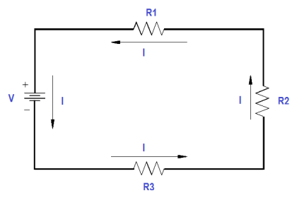
As we have already learned, Kirchhoff’s Laws provide a practical means to solve for unknowns in a circuit. Kirchhoff’s current law states that at any junction point in a circuit, the current arriving is equal to the current leaving. In a series circuit the current is the same at all points in that circuit. In parallel circuits, the total current is equal to the sum of the currents in each branch. Kirchhoff’s voltage law states that the sum of all potential differences in a closed loop equals zero.

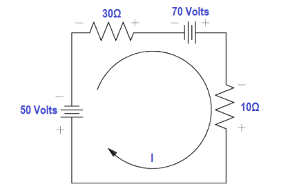
Using Kirchhoff’s laws, it is possible to take a circuit with two loops and several power sources (Figure 37) and determine loop equations, solve loop currents, and solve individual element currents.

Circuit for Loop Equations

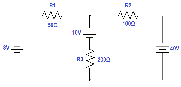
Figure 37 Example Circuit for Loop Equations

The first step is to draw an assumed direction of current flow (Figure 38). It does not matter whether the direction is correct. If it is wrong, the resulting value for current will be negative.

Assumed Direction of Current Flow

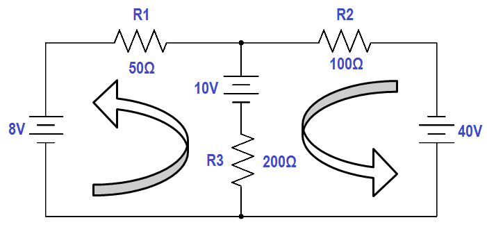
Figure 38 Assumed Direction of Current Flow

Second, mark the polarity of voltage across each component (Figure 39). It is necessary to choose a direction for current through the center leg, but it is not necessary to put in a new variable. It is simply I2 – I1

Marking Polarity

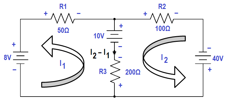
Figure 39 Marking Polarity

Third, apply Kirchhoff’s voltage law to loops one and two by picking a point in each loop and writing a loop equation of the voltage drops around the loop; then set the equation equal to zero.

Applying Voltage Law to Loop

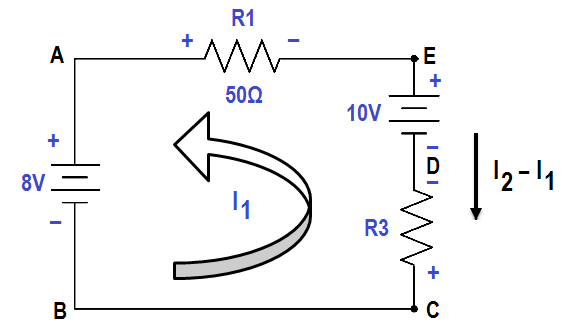
Figure 40 Applying Voltage Law to Loop 1

Figure 40 shows Loop one. From Point A to Point B, there is an increase in voltage of 8 volts. From Point C to Point D, there is an increase in voltage of 200 (I2 -I1). From Point D to Point E, there is a decrease in voltage of 10 volts. From Point E to Point A, there is a voltage decrease of 50I1 volts. The result in equation form is illustrated in below equation 1.

8 + 200 (I2 – I1) – 50I1 – 10 = 0

Using the same procedure for Loop 2 of Figure 39, the resulting equation is shown in below equation 2

10 – 200 (I2 – I1) + 40 – 100I1 = 0

Fourth, solve equations (1) and (2) simultaneously. First, rearrange and combine like terms in the equation for Loop 1.

-50 I1 + 200 I2 – 200 I1 = 10 – 8

-250 I1 + 200 I2 =2

Divide both sides by two.

-125 I1 + 100 I2 = 1

Rearrange and combine like terms in the Loop 2 equation.

-200 I2 + 200 I1 – 100 I2 = -10 -40

200 I1 – 300 I2 = -50

Multiplying the Loop 1 equation by 3,

3 (-125 I1 + 100 I2 = 1 )

and add it to the Loop 2 equation.

-375 I1 + 300 I2 = 3

200 I1 – 300 I2 = -50

– – – – – – – – – – – – – – – – –

– 175 I1 + 0 = – 47

– – – – – – – – – – – – – – – – –

Solving for I1 :

– 175 I1 = – 47

I1 = – 47 / -175 = 0.2686 amp = 286.3 mA

Solving for I2 using the Loop 1 equation:

– 125 (0.2686) + 100 I2 = 1

100 I2 = 1 + 33.58

I2 = 0.3458 amp = 345.8 mA

The current flow through R1 (50Ω) is I1 . The current flow through R2 (100Ω) is I2 , and through R3 (200Ω) is I2 -I1

I3 = I2 – I1

I3 = 345.8 mA – 286.3 mA = 77.2 mA

Fifth, apply Ohm’s Law to obtain the voltage drops across Resistors R1, R2 , and R3 :

V1 = I1R1 = (0.2686 amps)(50Ω) = 13.43 Volts
V2 = I2R2 = (0.3458 amps)(l00Ω) = 34.58 Volts
V3 = (I2 – I1) R3 = (0.0772 amps)(200Ω) = 15.44 Volts

Sixth, check the calculations by applying Kirchhoff’s Laws:

Check 1: Apply Kirchhoff’s voltage law to the larger outer loop (Figure 41).

Applying Voltage Laws to Outer Loop

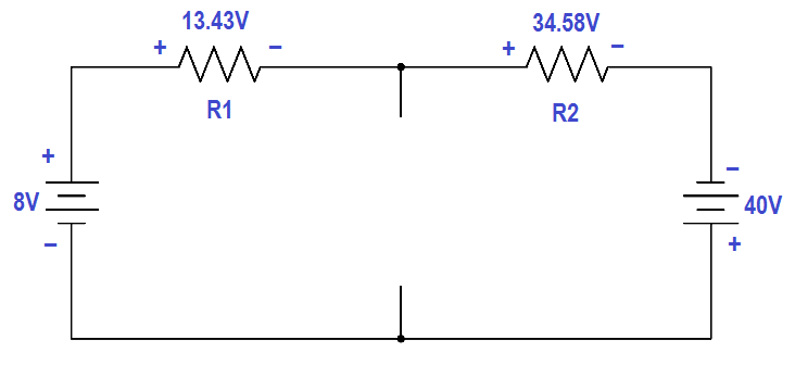
Figure 41 Applying Voltage Laws to Outer Loop

The sum of the voltage drops around the loop is essentially zero. (Not exactly zero due to rounding off.)

8 – 13.43 – 34.58 + 40 = 0

0.01 ≅ 0

Therefore, the solution checks.

Check 2: Use Kirchhoff’s current law at one of the junctions (Figure 42).

Applying Current Law to Junction

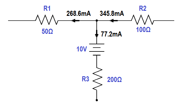
Figure 42 Applying Current Law to Junction

The sum of the currents out of the junction is:

0.2686 + 0.0772 = 0.3458 A = 345.8 mA

The current into the junction is 345.8 mA

The current into the junction is equal to the current out of the junction. Therefore, the solution checks.

Don't Miss Our Updates
Be the first to get exclusive content straight to your email.
We promise not to spam you. You can unsubscribe at any time.
Invalid email address
You've successfully subscribed !

Continue Reading

Series and Parallel Inductors
4-Wire, Three-Phase Wye Wiring System
Transformer Impedance Ratio
DC Machines Construction
Voltage Divider
AC Generation
Share This Article
Facebook Whatsapp Whatsapp LinkedIn Copy Link
Share
Leave a Comment

Leave a Reply Cancel reply

Your email address will not be published. Required fields are marked *

Stay Connected

128.3kFollowersLike
69.1kFollowersFollow
210kSubscribersSubscribe
38kFollowersFollow

Categories

Explore More

Calculate Power in Series RL Circuit
D’Arsonval Meter Movement
Transformer Voltage Ratio
DC Motor Theory
What is Electricity ?
Battery Terminology
Series Open Circuit Faults
Electrical Diagrams and Schematics

Keep Learning

Auto Transformer Schematic

Classification of Transformers

Basic AC Generator

AC Generator Parts

How to Measure Specific Gravity of Battery

How to Measure Specific Gravity of Battery

Transformer Operation Under No-Load

Transformer Operation Under No-Load

Cutaway View of Circuit Breaker

Low Voltage Air Circuit Breaker Principle

DC Machine

DC Generator Internal Losses

current division Formula for Resistor Circuit

Current Division

3φ AC Power Connections

Three Phase Systems

Learn More

Best 100 PLC Projects for Final Year Engineering Students

Best 100 PLC Projects for Final Year Engineering Students

What is a Mimic Panel

What is a Mimic Panel ?

HMI Simulation for PID Controller

PID Controller Output Types – PID_PWM and PID_Output

Ultrasonic level measurement

Ultrasonic Level Measurement

Pressure Transmitter Circuit

Pressure Transmitter Circuit

FIFO in STL Language in Siemens PLC

How to Code a FIFO Queue in STL Language in Siemens PLC?

Catalytic Gas Sensor Working

Catalytic Type Gas Sensor Principle

Turbine-Compressor System Architecture

Turbine-Compressor System Architecture

Menu

  • About
  • Privacy Policy
  • Copyright

Quick Links

  • Learn PLC
  • Helping Hand
  • Part Time Job

YouTube Subscribe

Follow US
All rights reserved. Reproduction in whole or in part without written permission is prohibited.
Welcome Back!

Sign in to your account

Username or Email Address
Password

Lost your password?