As an example of a split-ranged system with opposite valve failure modes, consider the following temperature control system supplying either hot water or chilled water to a “jacket” surrounding a chemical reactor vessel.
The purpose of this system is to either add or remove heat from the reactor as needed to control the temperature of its contents.
Chemical piping in and out of the reactor vessel has been omitted from this P&ID for simplicity, so we can focus just on the reactor’s temperature control system:
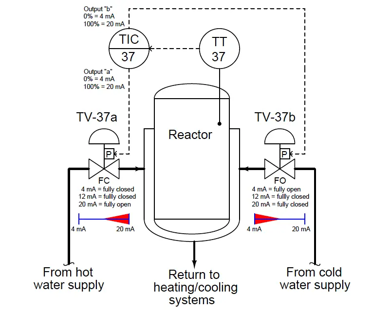
Here, the controller has been configured for dual-output operation, where the output value drives two identical 4-20 mA signals to the control valve positioners, which directly input the current signals from the controller without the need for I/P transducers in between.
The hot water valve (TV-37a) is fail-closed (FC) while the cold water valve (TV-37b) is fail-open (FO). Half-range positioner calibrations provide the exclusive sequencing necessary to ensure the two valves are never open simultaneously – TV-37b operates on the lower half of the 4-20 mA signal range (4-12 mA), while TV-37a operates on the upper half (12-20 mA).
Consider the effects from the controller (TIC-37) losing power. Both 4-20 mA signals will go dead, driving both valves to their fail-safe modes: hot water valve TV-37a will fully close, while cold water valve TV-37b will fully open.
Now consider the effects of air pressure loss to both valves. With no air pressure to operate, the actuators will likewise spring-return to their fail-safe modes:
once again hot water valve TV-37a will fully close, while cold water valve TV-37b will fully open.
In both failure events, the two control valves assume consistent states, ensuring maximum cooling to the reactor in the event of an output signal or instrument air failure.
However, suppose we desired both of these valves fail in the closed position in the event of an output signal or instrument air failure, rather than have the cooling valve fail open while the heating valve fails closed.
Clearly this would require both TV-37a and TV-37b to be fail-closed (FC), which would mean we must find some other way to sequence their operation to achieve split ranging.
Examine this reconfiguration of the reactor temperature control system, using identical control valves (signal-to-open, fail-closed) for both hot and cold water supply, and a controller with exclusively-sequenced 4-20 mA output signals:
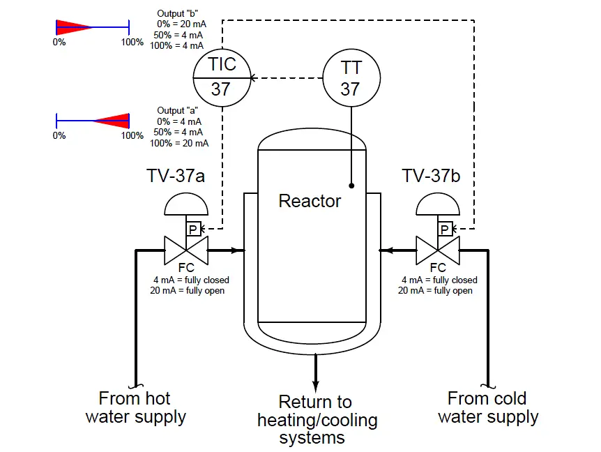
Consider the effects from the controller (TIC-37) losing power. Both 4-20 mA signals will go dead, driving both valves to their fail-safe modes: fully closed.
Now consider the effects of air pressure loss to both valves. With no air pressure to operate, the actuators will spring-return to their fail-safe modes: once again both control valves fully close.
In both failure events, the two control valves consistently close. The failure modes of both valves are still consistent regardless of the nature of the fault, but note how this scheme allows both valves to fail in the same mode if that is what we deem safest for the process.
As with all fail-safe system designs, we begin by choosing the proper fail-safe mode for each control valve as determined by the safety requirements of the process, not by what we would consider the simplest or easiest-to-understand instrument configurations.
Only after we have chosen each valve’s failure mode do we choose the other instruments’ configurations. This includes split-range sequencing: where and how we sequence the valves is a decision to be made only after the valves’ fail-safe states are chosen based on process safety.
Types of Control Valve Sequences
-
Complementary Control Valve Sequence
-
Exclusive Control Valve Sequence
-
Progressive Control Valve Sequence


Further more the Half-range positioner calibrations may provide further reassurance to ensure the two valves are never open simultaneously as follows– TV-37b operates on the lower half of the 4-20 mA signal range (4-11.95 mA), while TV-37a operates on the upper half (12.05-20 mA). Giving a 0.1mA assurance. This is not always nessesary, but worth noting
Malvern Jones,
In the case you described, could you please describe what happens when the current is 12 mA ?
Thanks.