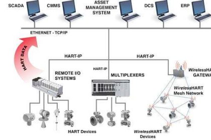
INSTALLATION AND GUIDELINES FOR HART NETWORKS
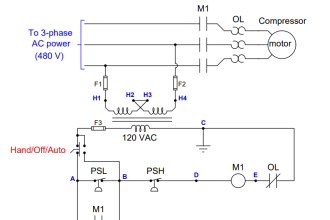
HART devices use the conventional 4–20 mA current signal cable path to send the HART FSK signal. Thus, no extra communication paths are required to send HART signals that use existing signal cables for communication. There are several ways to calculate HART cable lengths, which depend on the quality of cables used and consequently on the capacitance— the lower the cable capacitance, the longer would be the cable run. Capacitance limitation imposed by intrinsic safety considerations further puts a limit on the maximum cable run in such cases.
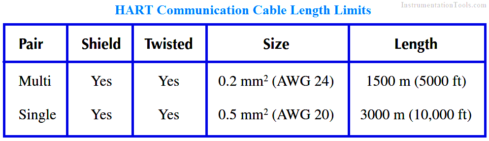
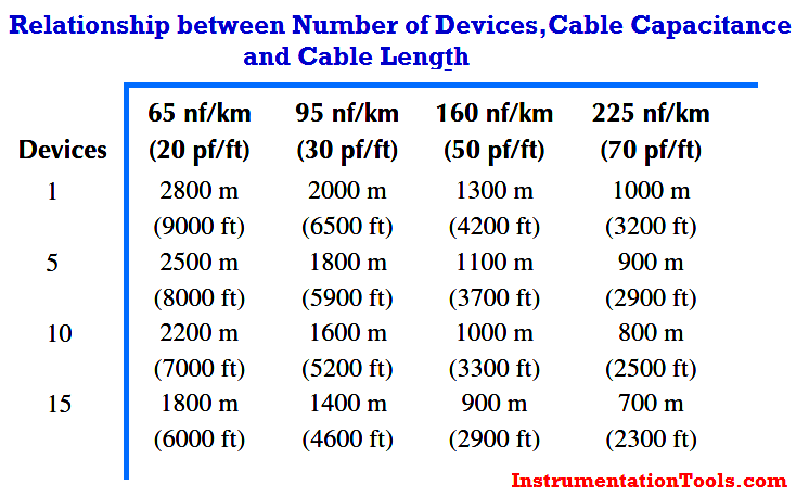
It is seen that HART communication is not vulnerable even for degraded cable quality. Cable length is dependent on its size (cross section) and also whether it is single- or multicore cable (Above Table). The below Table shows the influence of cable capacitance and number of devices on cable length.
DEVICE DESCRIPTIONS
The universal and command practice commands ensure interchangeability and openness of the field devices irrespective of the manufacturer. This is so when the user needs only standard status and the fault messages. The universal and command practice commands become insufficient if some device-specific information or some special properties of a device are required. The software of the master device has to adapt itself for such occasional device-related information or a new device is included in the system. This is where the Device Description Language (DDL) was developed.
The DDL is not limited to applications related to HART only, but can also be applied to other fieldbuses. The DDL was developed and specified, in a general way for fieldbuses, by the “Human Interface” workshop of the International Fieldbus Group (IFG). The DDL is a language—like a programming language—that enables the device manufacturers to describe all communications in a complete and comprehensive manner. It is a powerful tool that provides significant benefits during configuration and device-specific features.
DDL supports all extensions. Thus, any device- or manufacturer- specific command can be executed by DDL, and the user is provided with a universally applicable and uniform user interface. This thus entails a clear, user-friendly, and safer operation and monitoring of the process.
A DDL encoder reads the device description as binary-encoded DD data that can be read by a master device. If a device has sufficient storage space, the said DD can be stored in its firmware. During the parameterization phase, it can be read by the master device.