Inst ToolsInst ToolsInst Tools
  • Courses
  • Automation
    • PLC
    • Control System
    • Safety System
    • Communication
    • Fire & Gas System
  • Instrumentation
    • Design
    • Pressure
    • Temperature
    • Flow
    • Level
    • Vibration
    • Analyzer
    • Control Valve
    • Switch
    • Calibration
    • Erection & Commissioning
  • Interview
    • Instrumentation
    • Electrical
    • Electronics
    • Practical
  • Q&A
    • Instrumentation
    • Control System
    • Electrical
    • Electronics
    • Analog Electronics
    • Digital Electronics
    • Power Electronics
    • Microprocessor
  • Request
Search
  • Books
  • Software
  • Projects
  • Process
  • Tools
  • Basics
  • Formula
  • Power Plant
  • Root Cause Analysis
  • Electrical Basics
  • Animation
  • Standards
  • 4-20 mA Course
  • Siemens PLC Course
Reading: Control Valve Preventive Maintenance
Share
Font ResizerAa
Inst ToolsInst Tools
Font ResizerAa
  • Courses
  • Design
  • PLC
  • Interview
  • Control System
Search
  • Courses
  • Automation
    • PLC
    • Control System
    • Safety System
    • Communication
    • Fire & Gas System
  • Instrumentation
    • Design
    • Pressure
    • Temperature
    • Flow
    • Level
    • Vibration
    • Analyzer
    • Control Valve
    • Switch
    • Calibration
    • Erection & Commissioning
  • Interview
    • Instrumentation
    • Electrical
    • Electronics
    • Practical
  • Q&A
    • Instrumentation
    • Control System
    • Electrical
    • Electronics
    • Analog Electronics
    • Digital Electronics
    • Power Electronics
    • Microprocessor
  • Request
Follow US
All rights reserved. Reproduction in whole or in part without written permission is prohibited.
Inst Tools > Blog > Control Valves > Control Valve Preventive Maintenance

Control Valve Preventive Maintenance

In this article we will discuss how to do proper preventive maintenance (PM) activity for a Control Valve and other important points.

Last updated: May 31, 2022 9:30 am
Editorial Staff
Control Valves
No Comments
Share
6 Min Read
SHARE

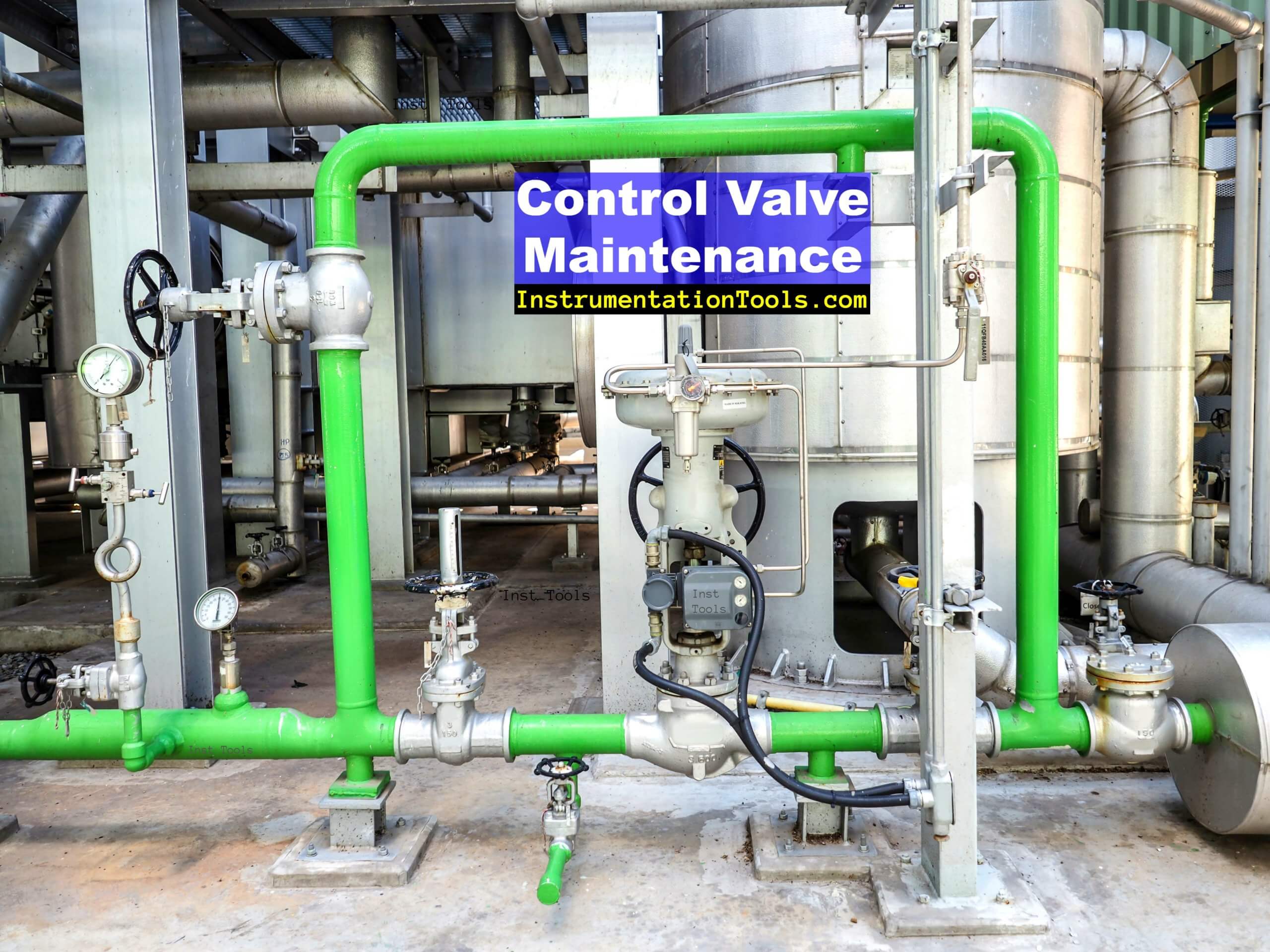
Today in this article we will discuss how to do proper preventive maintenance (PM) activity for a Control Valve. Because many times we miss important things that should be checked.

Contents
Control Valve ActivitiesControl Valve Preventive Maintenance ProcedurePM Checklist

Control Valve Activities

Activities to do before starting the PM job (preventive maintenance) are:

Ensure a proper work permit is available for the respective control valve in which the PM job is to be done

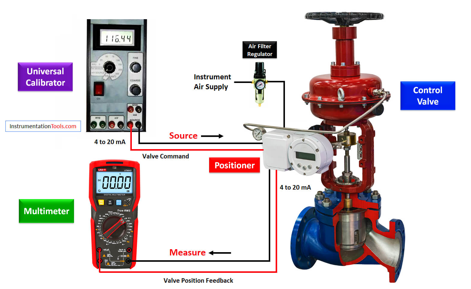
Following Test and Calibration Instruments (TCI = Test and Calibration Instruments) to be kept ready.

  • Digital Multimeter
  • HART 375/475
  • mA source or Beamex
  • Tool bag with all necessary tools

Always check all these Tests and Calibration Instrument’s operational status one day before the PM job. If any of the Test and Calibration Instrument is not charged then charge them before the job like HART communication.

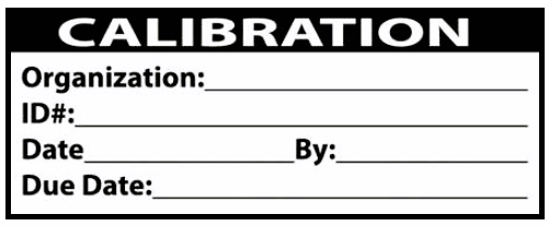
Also, make sure that Test and Calibration Instruments are calibrated and check their validity. One sample of the calibration sticker which is attached to every Test and Calibration Instrument is shown below.

calibration sticker

Identify the hazards one day before the job. Carry all mandatory personal protective equipment (PPE) and special PPE if required.

Check the valve fail action and Air Filter Regulator (AFR) set pressure from the data sheet of the control valve.

Control Valve Preventive Maintenance Procedure

Control Valve Preventive Maintenance
  1. Take appropriate work permits and take necessary approvals.
  2. Inform operation engineers regarding the control valve stroke check activity that we will do during the PM job so that they can prepare accordingly.
  3. If there are any interlocks, then inform the operation engineers and force the required logic and log the activity.
  4. The first step is to check the air pressure in the AFR and confirm its value with the air pressure mentioned in the control valve datasheet.
  5. Now using a snoop liquid leak detector (or any other leak detector) check all the air tubing and all the connections for air leakage.
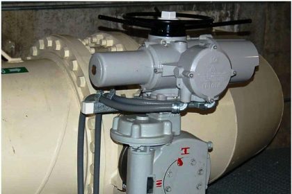
  6. Open the control valve positioner’s cover and check the tightness of all the cable connections. Also, if I to P converter is used, then check cable connection tightness in I to P also. If the cable lugs are not proper, the cable relugging is to be done.
  7. Check the supply voltage.
  8. If the feedback to the valve positioner is through the mechanical link, then check its condition. If the mechanical link is corroded then replace the mechanical link. Also check other valve accessory’s condition (Air volume booster, trip valve, quick exhaust valve, etc. if available).
  9. Isolate the instrument supply air and vent the remaining air in the supply line to check the control valve fail action.
The Control Valve Stroke Test Procedure

10. Restore the instrument air tubing after making the valve normal, and check the fail action after removing the signal cable.

11. Now ask the control room operator to give commands from 0% to 100% with increments. In general, we use 0%, 25%, 50%, 75%, 100% calibration points.

Similarly, check the valve stroke in decrement from 100% to 0% in steps. If there is no facility to give input from the control room, then connect the HART communicator or mA source or Beamex to the control valve for giving the commands from the field directly.

Note down values as shown in the table:

Control Valve Stroke CheckField ValueDCS/SCADA/PLC Value
0  
25  
50  
75  
100  
75  
50  
25  
0  

12. If valve command vs travel and feedback is not satisfactory, then do the calibration of the control valve. Again repeat from step 9, if calibration is done.

13. Apply a calibration sticker on the Control Valve with the appropriate due date.

14. Clean the Control Valve.

15. Normalize the logic if forced. Close the work permit.

15. Fill up the calibration record.

PM Checklist

The following are the PM checklist points that need to be filled:

  1. Tag number of Instrument
  2. Order Number
  3. Permit Number
  4. Date of Calibration
  5. Air Pressure
  6. Fail Action
  7. Position before doing Job
  8. Position after doing Job
  9. Control Valve Make & Model number
  10. Test and Calibration Instrument used
  11. Test Result
  12. Technicians involved in Job
  13. Engineers involved in Job

If you liked this article, then please subscribe to our YouTube Channel for Instrumentation, Electrical, PLC, and SCADA video tutorials.

You can also follow us on Facebook and Twitter to receive daily updates.

Read Next:

  • Repair of Control Valve
  • Types of Pneumatic Valves
  • Protect Pumps from Cavitation
  • Pressure Relief Valve Principle
  • Valve Multiple Choice Questions
Don't Miss Our Updates
Be the first to get exclusive content straight to your email.
We promise not to spam you. You can unsubscribe at any time.
Invalid email address
You've successfully subscribed !

Continue Reading

DIN Valve Connectors – Definition, Types
Effect of Differential Pressure on Control Valve Lift
Difference between Butterfly Valves and Ball Valves
Types of Pneumatic Valves : Poppet & Spool
Control Valve Installation, Maintenance, Disassembly & Reassembly
How Needle Valve Works ?
Share This Article
Facebook Whatsapp Whatsapp LinkedIn Copy Link
Share
Leave a Comment

Leave a Reply Cancel reply

Your email address will not be published. Required fields are marked *

Stay Connected

128.3kFollowersLike
69.1kFollowersFollow
210kSubscribersSubscribe
38kFollowersFollow

Categories

Explore More

Control Valves Mechanical Friction Problems
Valve Safety Factor
Identify Valve Parts Quiz with Answers
How to Troubleshoot Control Valve? – Problems and Solutions
Solving Control Valve Hunting: Instrument Troubleshooting
Control Valve in Nutshell – Valve Design and Selection Factors
Pneumatic Valve Positioner Working Principle
Globe Valve Seat and Disk

Keep Learning

Electric Solenoid Actuators Principle

What is a Electric Solenoid Actuator ?

Questions and Answers on Valves

Valve Quiz

Solenoid Valve

Solenoid Valve Troubleshooting Practices

What is Swing Check Valve ?

Control Valve Calibration

How-to do Control Valve Calibration?

Hydraulic Actuator

Types of Valve Actuators

Pressure Control Valve

What is Pressure Control Valve?

radial-vane damper

Dampers and Louvres

Learn More

Industrial Automation and Control Systems (IACS)

Industrial Automation and Control Systems (IACS)

PLC Program for Conditional Control Logic

PLC Program for Conditional Control Logic

SIS Failures and Reliability - Safety Instrumented Systems

SIS Failures and Reliability – Safety Instrumented Systems

Electrical Machines Short Answers

Electrical Machines Short Answers

Aluminum Cable Terminations

Aluminum Cable Terminations Repeat Failures

Venturi Flow Meter Theory

Basics of Venturi Flow Meter

PLC Interview Questions and Answers

PLC Interview Questions and Answers

Difference Between Process and Project

Difference Between Process and Project

Menu

  • About
  • Privacy Policy
  • Copyright

Quick Links

  • Learn PLC
  • Helping Hand
  • Part Time Job

YouTube Subscribe

Follow US
All rights reserved. Reproduction in whole or in part without written permission is prohibited.
Welcome Back!

Sign in to your account

Username or Email Address
Password

Lost your password?