Inst ToolsInst ToolsInst Tools
  • Courses
  • Automation
    • PLC
    • Control System
    • Safety System
    • Communication
    • Fire & Gas System
  • Instrumentation
    • Design
    • Pressure
    • Temperature
    • Flow
    • Level
    • Vibration
    • Analyzer
    • Control Valve
    • Switch
    • Calibration
    • Erection & Commissioning
  • Interview
    • Instrumentation
    • Electrical
    • Electronics
    • Practical
  • Q&A
    • Instrumentation
    • Control System
    • Electrical
    • Electronics
    • Analog Electronics
    • Digital Electronics
    • Power Electronics
    • Microprocessor
  • Request
Search
  • Books
  • Software
  • Projects
  • Process
  • Tools
  • Basics
  • Formula
  • Power Plant
  • Root Cause Analysis
  • Electrical Basics
  • Animation
  • Standards
  • 4-20 mA Course
  • Siemens PLC Course
Reading: Pneumatic Valve Positioner Working Principle
Share
Font ResizerAa
Inst ToolsInst Tools
Font ResizerAa
  • Courses
  • Design
  • PLC
  • Interview
  • Control System
Search
  • Courses
  • Automation
    • PLC
    • Control System
    • Safety System
    • Communication
    • Fire & Gas System
  • Instrumentation
    • Design
    • Pressure
    • Temperature
    • Flow
    • Level
    • Vibration
    • Analyzer
    • Control Valve
    • Switch
    • Calibration
    • Erection & Commissioning
  • Interview
    • Instrumentation
    • Electrical
    • Electronics
    • Practical
  • Q&A
    • Instrumentation
    • Control System
    • Electrical
    • Electronics
    • Analog Electronics
    • Digital Electronics
    • Power Electronics
    • Microprocessor
  • Request
Follow US
All rights reserved. Reproduction in whole or in part without written permission is prohibited.
Inst Tools > Blog > Control Valves > Pneumatic Valve Positioner Working Principle

Pneumatic Valve Positioner Working Principle

Last updated: May 26, 2020 11:14 am
Editorial Staff
Control Valves
1 Comment
Share
3 Min Read
SHARE

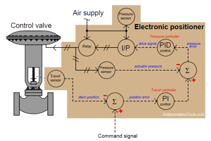
The Pneumatic Valve Positioner is an instrument working on force balance principle to position the Control Valve stem in accordance to a pneumatic signal received from a controller or manual loading station, regardless of packing box friction, actuator hysteresis or unbalanced forces on the valve plug. Thus, the positioner ensures a reliable and accurate operation of Control Valve.

Contents
Pneumatic Valve PositionerDirect Acting Control Valve PositionerReverse Acting Control Valve Positioner

Pneumatic Valve Positioner

The Valve Positioner is force balance device which, ensure the position of the plug, which is directly proportional to the controller output pressure. The Positioner compares the forces generated by the control signal and the control valve stem through the motion connector and the feed back cam, and accordingly it feeds or bleeds the air going to the valve actuator.

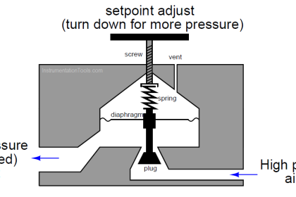
The instrument air signal is applied to the signal diaphragm. An increase in signal will drive the diaphragm and flapper-connecting stem to the right. The flapper-connecting stem will then open the supply flapper admitting supply pressure into the output which is connected to the actuator diaphragm.

The exhaust flapper remains closed when the flapper connecting stem is deflected to right. The effect of increasing signal is to increase the pressure in the actuator. This increased pressure in the actuator drives the valve stem downward and rotates the positioner lever clockwise.

This clockwise rotation of the lever results in a compression of range spring through cam. When the valve stem reaches the position called for by the controller, the compression in the range spring will give a balance force resulting the closure of both the flapper.

If the control signal is decreased, the force exerted by the signal diaphragm will also decrease and the force from the range spring will push the flapper-connecting stem to the left, opening the exhaust flapper. This causes a decrease actuator diaphragm pressure and allows the valve stem to move upward until a new force balance is established.

Direct Acting Control Valve Positioner

Direct Acting Control Valve Positioner

Reverse Acting Control Valve Positioner

Reverse Acting Control Valve Positioner Principle

Source : pneuconvalves

Articles You May Like :

What is a Control Loop ?

Single Acting Actuators

Bellows Seal Valve 

Electric Actuator Parts

Control Valve Software

Don't Miss Our Updates
Be the first to get exclusive content straight to your email.
We promise not to spam you. You can unsubscribe at any time.
Invalid email address
You've successfully subscribed !

Continue Reading

What are Isolation valves? – Purpose, Types, Configurations
What is a Disc Valve ?
Advantages and Disadvantages of Valve Actuators
Difference between Butterfly Valves and Ball Valves
Direct Lift Diaphragm Solenoid Valve Principle
What is Double-ported Globe Valve ?
Share This Article
Facebook Whatsapp Whatsapp LinkedIn Copy Link
Share
1 Comment
  • Engr. Md. Habibur Rahman says:
    January 12, 2017 at 4:34 pm

    Very nice diagramme & more and more diagramme I want to watching on facebook.

    Reply

Leave a Reply Cancel reply

Your email address will not be published. Required fields are marked *

Stay Connected

128.3kFollowersLike
69.1kFollowersFollow
210kSubscribersSubscribe
38kFollowersFollow

Categories

Explore More

Pilot-operated Relief Valve Principle
Control Valve Selection Guide
Control Valves Chemical attack Problems
Difference between Quick Opening, Linear & Equal Percentage Control Valve characteristics
Butterfly Valves Construction, Types, Stem & Bonnet Assembly
What is Poppet Valve? When we Use a Poppet Valve?
What is Instrument Air Manifold ?
What is Pinch Valve ?

Keep Learning

Globe Control Valve Animation

Basics of Globe Valves

Parallel Disk Gate Valve

Classification of Gate Valves

Valve Bellows seal

Bellows Seal Valve Working Principle

Pneumatic Piping Design and Specification

Pneumatic Piping Design and Specification

Control Valve in Nutshell - Valve Design and Selection Factors

Control Valve in Nutshell – Valve Design and Selection Factors

Gate Valve

How Gate Valves Work ?

needle valve applications

Applications of Needle Valves

How is pressure drop calculated through a valve?

How is Pressure Drop Calculated through a Valve ?

Learn More

factorytalk view studio hmi

How to Create Templates in FactoryTalk View Studio?

Linear Variable Displacement Transducer (LVDT)

What is LVDT ?

Dry Leg

Calculate 0%, 50%, and 100% Calibration Points for ΔP transmitter

SIS Failures and Reliability - Safety Instrumented Systems

SIS Failures and Reliability – Safety Instrumented Systems

PLC Ladder Logic Example

PLC Ladder Logic Example

Process Control Instrumentation Objective Questions

Process Control & Instrumentation Objective Questions – Set 5

Lime Slaker

Advancements in Lime Slaking Technology: What’s New And What’s Next

Working of Proximitor

Different Types of Turbine Protective Devices

Menu

  • About
  • Privacy Policy
  • Copyright

Quick Links

  • Learn PLC
  • Helping Hand
  • Part Time Job

YouTube Subscribe

Follow US
All rights reserved. Reproduction in whole or in part without written permission is prohibited.
Welcome Back!

Sign in to your account

Username or Email Address
Password

Lost your password?