Control Valves are meant to control the process parameters namely Pressure, Flow, Level and Temperature.
Control Valve is the final control element in any closed-loop control. Based on their application type they are named as Pressure Control Valve, Level Control Valve, and Temperature Control Valve.
Calibration is the quantitative determination of errors of a measuring device and, where necessary, adjusting these errors to a minimum. The error is comparison with higher standard having traceability to National or International standard.
Control Valve Calibration

Following the receipt of the Work Request which is generated through SAP, the instrument engineer will submit Safety Document Request (Generated by SAP) one day in advance for the work planned. Some Industries will use manual work permit systems in the absence of SAP.
Confirm isolation before receiving the safety document.
Check the interlock in the relevant logic diagram for the valve to be stroked. Simulate or force the necessary signal like valve position etc to ensure safe operation of the process before starting the job.
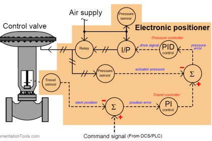
Check the healthiness of I/P Converter, Position feedback transmitter, airlock relay, solenoid valve, and air supply pressure.
Check the manual operation of the valve using the hand wheel. Stroke the valve either from local or from DCS as applicable. Confirm the valve travel from local. Calibrate the Valve with the inbuilt option like “Auto Calibration” available in the valve positioner. Also, check the Limit switches function and adjust them as required.
For the SMART Control Valve, we can use a HART communicator to calibrate the control valve. Give the supply pressure according to the valve as per nameplate details. Connect the HART to the valve positioner. Then go to valve simulate command, enter 0% and observe the valve position. Next, enter 25% in HART and observe the valve travel position.
Similarly, enter 50%, 75% and 100% in the HART communicator then observe the valve stem travel position accordingly. You can find a manual scale (0% to 100%) with a needle on the valve to verify the valve travel position.
Confirm the signal status and remove all the simulation/forces, which were done before starting the job.
Clear and return the work Permit to the Plant Shift Manager. Update the Work Order in SAP.
Share your experience with us on the Calibration of Control Valves, use the comments section.


In addition to the Calibration, it is also crucial that the Control Valve (CV) response matches the demands of the controller.
Normally, the CV is calibrated and checked as already mentioned in this post, but please appreciate that in real operation, for most of the time the controller output will change in very minor amount to counteract the process upsets or setpoint changes and the CV need to respond rapidly and effectively to those changes.
Thus if you observe any CV, or note its trend from the Control System, you will see movements in fractions of mA/psi, etc. Very few CVs will go to the full closed position and the valve going to the fully open position is even rarer. Also, it is necessary that the CV overcomes any stiction, has minimum hysteresis as well as the little dead band.
Therefore, it is important the valve be checked for minor changes.
How to check Control Valve:
Move the valve to any position other than at its extremes, somewhere in the middle.
Find a safe spot on the CV stem where you can feel the minor CV movement against a fixed part of the CV Body.
Put your finger firmly on that spot of the CV Stem. I repeat “SAFE SPOT,” otherwise if the CV operates suddenly your finger may be injured.
If the CV has a digital positioned with feedback, the observation may be simpler and finger feeling may even be not necessary at all.
Now closely observe the CV input signal, preferably the pneumatic signal on a 6-inch dia pressure gauge of at least 0.5 % accuracy.
If a digital pressure indicator of similar or better accuracy is used that would be better.
While applying the input signal move the CV a small amount, then apply the reverse signal very gently and slowly, and feel the CV stem movement with your finger, the stem should move.
The numerical value of the input signal against the minor can be noted from the factory test data of the valve.
In case that is not available, it would be known by experience.
Repeat this exercise at two or different CV openings and always check in forward and reverse directions, till you are confident of the CV performance.
In case of valve sticks, shows excessive dead band etc, then loosening of the stem packing or even CV opening for inspection to check stem/plug misalignment, or hardened stem packing may be the culprit.
Wonderful article about control valve calibration.
Also, Mr. Ahmed’s comments are very much appreciated as it projects the real-life plant situation.
I think the Control valve calibration takes more tasks when it comes to Shutdown maintenance.
Typically in a Thermal power plant, during major overhauls, both the valve actuator and the control valves are being serviced by different teams.
Following are the typical points:
a. Taking as found calibration condition of the control valve before starting dismantling.
b. Conduct Leak Test (Bubble Test) on the Actuator Assembly to determine if there is any air leak
c. Checking the Handwheel operation and dismantling servicing of Handwheel Assembly and replacing parts as required.
d. Decoupling valve stem and actuator stem and allow the valve group to complete their work.
e. Servicing of the valve actuator and accessories like positioner, volume booster, air filter regulator solenoids, air lock relay etc. Replace diaphragm or piston o rings for the actuator depending on the type of actuator.
f. After valve overhauling is completed, refit the actuator, couple valve, and actuator stem and complete bench test.
g. Fix the Actuator Assembly and check the manual operation.
h. Check valve calibration as per steps indicated in the article ( Instrumentation Tools)
I am glad to share the points based on field experience. Any correction if needed is welcome.
I really appreciate the wonderful service this forum ” Instrumentation Tools” is doing for the Instrument people.
Thank you K Sreenivasan and Ahmed for sharing the insights on control valves
What is difference in actual CV , selected CV and design CV
Nice article
Standard of control valve calibration should follow these steps
Step 1- To ensure the main valve position base on the valve indicator is correct. (How you know the valve plug is just “enough” toughing to the seat when valve position is pointed to zero ?)
Step 2- Bench test and calibration check, some of the spring is fixed range. (From where you find out the spring set points)
Step 3- To install a valve positioner. (Why we need to force the main valve at 50% position, when using instrument air “direct” inject and adjust the air pressure to the valve actuator)
Step 5- Valve positioner calibration. (Why before calibrate we need to check the positioner format ?)
What is Dome Valve ? | Principle, Features and Valves
Dome Valve is Used in the Pneumatic Phase Dense Conveying Application. An isolation valve used in many applications where conventional valves like ball valve, butterfly valve and slide gate.
Good article !
Am interested about the instrumentation and control,operating principle of philosophy both calibration and control system,Dcs,Scada,both pas and sis etc.