Inst ToolsInst ToolsInst Tools
  • Courses
  • Automation
    • PLC
    • Control System
    • Safety System
    • Communication
    • Fire & Gas System
  • Instrumentation
    • Design
    • Pressure
    • Temperature
    • Flow
    • Level
    • Vibration
    • Analyzer
    • Control Valve
    • Switch
    • Calibration
    • Erection & Commissioning
  • Interview
    • Instrumentation
    • Electrical
    • Electronics
    • Practical
  • Q&A
    • Instrumentation
    • Control System
    • Electrical
    • Electronics
    • Analog Electronics
    • Digital Electronics
    • Power Electronics
    • Microprocessor
  • Request
Search
  • Books
  • Software
  • Projects
  • Process
  • Tools
  • Basics
  • Formula
  • Power Plant
  • Root Cause Analysis
  • Electrical Basics
  • Animation
  • Standards
  • 4-20 mA Course
  • Siemens PLC Course
Reading: Practical Calibration Standards
Share
Font ResizerAa
Inst ToolsInst Tools
Font ResizerAa
  • Courses
  • Design
  • PLC
  • Interview
  • Control System
Search
  • Courses
  • Automation
    • PLC
    • Control System
    • Safety System
    • Communication
    • Fire & Gas System
  • Instrumentation
    • Design
    • Pressure
    • Temperature
    • Flow
    • Level
    • Vibration
    • Analyzer
    • Control Valve
    • Switch
    • Calibration
    • Erection & Commissioning
  • Interview
    • Instrumentation
    • Electrical
    • Electronics
    • Practical
  • Q&A
    • Instrumentation
    • Control System
    • Electrical
    • Electronics
    • Analog Electronics
    • Digital Electronics
    • Power Electronics
    • Microprocessor
  • Request
Follow US
All rights reserved. Reproduction in whole or in part without written permission is prohibited.
Inst Tools > Blog > Calibration > Practical Calibration Standards

Practical Calibration Standards

Last updated: May 19, 2019 11:19 am
Editorial Staff
Calibration
No Comments
Share
6 Min Read
SHARE

As previously defined, calibration refers to the checking and adjustment of an instrument so that its output faithfully corresponds to its input throughout a specified range.

In order to calibrate an instrument, we must have some means of knowing the input and/or output quantities associated with the instrument under test.

A substance or device used as a reference to compare against an instrument’s response is called a calibration standard. Simply put, a calibration standard is something we may compare the calibrated instrument to. Thus, any calibration can only be as good as the standard used.

Calibration standards fall into two broad categories: standards used to produce accurate physical quantities (e.g. pressure, temperature, voltage, current, etc.), and standards used to simply measure physical quantities to a high degree of accuracy.

An example of the former would be the use of boiling water (at sea level) to produce a temperature of 100 degrees Celsius (212 degrees Fahrenheit) in order to calibrate a temperature gauge, whereas an example of the latter would be the use of a laboratory-quality precision thermometer to measure some arbitrary source of temperature in comparison to the temperature gauge being calibrated.

In metrology labs, the ultimate standards are based on fundamental constants of nature, and are called intrinsic standards. A modern example of an intrinsic standard for time is the so-called atomic clock, using isolated atoms of Cesium to produce frequencies which are inherently fixed and reproduceable world-wide.

Instrument shops located in industrial facilities cannot afford the capital and consumable costs associated with intrinsic standards, and so must rely on other devices for their calibration purposes.

Ideally, there should be a “chain” of calibration from any device used as a shop standard traceable all the way back to some intrinsic standard in a national-level or primary metrology lab.

Calibration standards used in instrument shops for industrial calibration work should therefore be periodically sent to a local metrology lab for re-standardization, where their accuracy may be checked against other (higher-level) standards which themselves are checked against even higher level calibration standards, ultimately traceable all the way to intrinsic standards. In each step of the calibration “chain,” there is a progressive degree of measurement uncertainty.

Intrinsic standards possess the least amount of uncertainty, while field instruments (e.g. pressure transmitters, temperature gauges, etc.) exhibit the greatest uncertainties.

It is important that the degree of uncertainty in the accuracy of a test instrument is significantly less than the degree of uncertainty we hope to achieve in the instruments we calibrate.

Otherwise, calibration becomes a pointless exercise. This ratio of uncertainties is called the Test Uncertainty Ratio, or TUR.

A good rule-of-thumb is to maintain a TUR of at least 4:1 (ideally 10:1 or better), the test equipment being many times more accurate (less uncertain) than the field instruments we calibrate with them.

I have personally witnessed the confusion and wasted time that results from trying to calibrate a field instrument to a tighter tolerance than what the calibration standard is capable of.

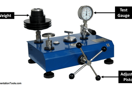
In one case, an instrument technician attempted to calibrate a pneumatic pressure transmitter to a tolerance of ± 0.25% of span using a test gauge that was only good for ± 1% of the same span.

This poor technician kept going back and forth, adjusting the transmitter’s zero and span screws over and over again in a futile attempt to reign in the transmitter’s response within the stated specification of ± 0.25%.

After giving up, he tested the test gauges by comparing three of them at once, tied together on a common air pressure tube. When he did this, it became clear that no two test gauges would consistently agree with each other within the specified tolerance over the 3 to 15 PSI range.

As he raised and lowered the pressure, the gauges’ indications would deviate from one another far more than ± 0.25% across the measurement range.

Simply put, the inherent uncertainty of the gauges exceeded the uncertainty he was trying to calibrate the transmitter to.

As a result, his calibration “standard” was in fact shifting on him as he performed the calibration. His actions were analogous to trying to set up a fixed-position cannon to repeatedly hit a moving target.

The lesson to be learned here is to always ensure the standards used to calibrate industrial instruments are reliably accurate (enough).

No calibration standard is perfect, but perfection is not what we need. Our goal is to be accurate enough that the final calibration will be reliable within specified boundaries.

Don't Miss Our Updates
Be the first to get exclusive content straight to your email.
We promise not to spam you. You can unsubscribe at any time.
Invalid email address
You've successfully subscribed !

Continue Reading

Stroke Checking Procedure for GCV, SRV, IGV, and LFBV
List of Documents Required for Testing and Calibration Laboratories
Selection of Master Instrument for Calibration
Nuclear Interface Level Measurement Principle, Limitations, Installation and Calibration
Ammonia Gas Detector Working Principle and Calibration
Pressure Safety Valve Leak Test Procedure (PSV Testing)
Share This Article
Facebook Whatsapp Whatsapp LinkedIn Copy Link
Share
Leave a Comment

Leave a Reply Cancel reply

Your email address will not be published. Required fields are marked *

Stay Connected

128.3kFollowersLike
69.1kFollowersFollow
210kSubscribersSubscribe
38kFollowersFollow

Categories

Explore More

How to Commission WirelessHART Transmitter With Gateway
Turbidity Sensor Calibration Procedure
Motor Operated Valve Functional Testing
Pressure Gauge Functional Testing
Calibration and Troubleshooting of Oxygen Analyzer
What is Bump Testing ?
Pressure Transmitter Calibration at the bench
Closed tank DP Level Transmitter with wet leg elevation zero direct mount Calibration

Keep Learning

transmitter calibration procedure

Transmitter Calibration Procedure

Fieldbus Transmitter Calibration

Fieldbus Transmitters Calibration and Ranging

Pressure transmitter Calibration Setup

Instruments Calibration Procedures

pressure-switch-calibration-procedure

Pressure Switch Calibration Procedure

ORP-sensor-calibration

Oxidation-Reduction Potential (ORP) Sensor Calibration Procedure

Calibration & Preventative Maintenance Procedures

Calibration and Preventative Maintenance Procedures

Differential Pressure Switch Calibration Procedure - Copy

Differential Pressure Switch Calibration Procedure

How to Calibrate pH Electrode?

How to Calibrate pH Electrode?

Learn More

Types of Inductors

What is an Inductor? – Types of Inductors

power factor correction equipment

Power Factor Controller (PFC) – Commissioning

Vibration Probe Field Setting Procedure

Vibration Probe Field Setting Procedure

Gas Detectors Calibration

Calibration of Gas Detectors

pressure switch control two lamps wiring

Draw Wiring of a Pressure Switch to control two lamps

PCB Assembly

Five Types of PCB Assembly that You Should Know

Ethernet IP Preferred in Large Networking Systems

Why is Ethernet IP Preferred in Large Networking Systems?

DCS Quiz

DCS Quiz

Menu

  • About
  • Privacy Policy
  • Copyright

Quick Links

  • Learn PLC
  • Helping Hand
  • Part Time Job

YouTube Subscribe

Follow US
All rights reserved. Reproduction in whole or in part without written permission is prohibited.
Welcome Back!

Sign in to your account

Username or Email Address
Password

Lost your password?