WHAT IS CALIBRATION?
Typically, calibration of an instrument is checked at several points throughout the calibration range of the instrument. The calibration range is defined as “the region between the limits within which a quantity is measured, received or transmitted, expressed by stating the lower and upper range values.” The limits are defined by the zero and span values.
The zero value is the lower end of the range. Span is defined as the algebraic difference between the upper and lower range values. The calibration range may differ from the instrument range, which refers to the capability of the instrument. For example, an electronic pressure transmitter may have a nameplate instrument range of 0–750 pounds per square inch, gauge (psig) and output of 4-to-20 milliamps (mA). However, the engineer has determined the instrument will be calibrated for 0-to-300 psig = 4-to-20 mA. Therefore, the calibration range would be specified as
0-to-300 psig = 4-to-20 mA. In this example, the zero input value is 0 psig and zero output value is 4 mA. The input span is 300 psig and the output span is 16 mA.
WHAT ARE THE CHARACTERISTICS OF A CALIBRATION?
Tolerance: Permissible deviation from a specified value; may be expressed in measurement units, percent of span, or percent of reading.
The calculated tolerance is rounded down to 0.10 mA, because
Example: The process requires ±5°C; available test equipment is capable of ±0.25°C; and manufacturer’s stated accuracy is ±0.25°C. The specified calibration tolerance must be between the process requirement and manufacturer’s specified tolerance. Additionally the test equipment must be capable of the tolerance needed. A calibration tolerance of ±1°C might be assigned for consistency with similar instruments and to meet the recommended accuracy ratio of 4:1.
Suppose we use our previous example of the test equipment with a tolerance of ±0.25°C and it is found to be 0.5°C out of tolerance during a scheduled calibration. Since we took into consideration an accuracy ratio of 4:1 and assigned a calibration tolerance of ±1°C to the process instrument, it is less likely that our calibration performed using that standard is compromised.
The out-of-tolerance standard still needs to be investigated by reverse traceability of all calibrations performed using the test standard. However, our assurance is high that the process instrument is within tolerance. If we had arbitrarily assigned a calibration tolerance of ±0.25°C to the process instrument, or used test equipment with a calibration tolerance of ±1°C, we would not have the assurance that our process instrument is within calibration tolerance. This leads us to traceability.
Traceability: All calibrations should be performed traceable to a nationally or internationally recognized standard. For example, in the United States, the National Institute of Standards and Technology (NIST), formerly National Bureau of Standards (NBS), maintains the nationally recognized standards. Traceability is defined by ANSI/NCSL Z540-1-1994 (which replaced MIL-STD-45662A) as “the property of a result of a measurement whereby it can be related to appropriate standards, generally national or international standards, through an unbroken chain of comparisons.” Note this does not mean a calibration shop needs to have its standards calibrated with a primary standard. It means that the calibrations performed are traceable to NIST through all the standards used to calibrate the standards, no matter how many levels exist between the shop and NIST.
The calibration technician’s role in maintaining traceability is to ensure the test standard is within its calibration interval and the unique identifier is recorded on the applicable calibration data sheet when the instrument calibration is performed. Additionally, when test standards are calibrated, the calibration documentation must be reviewed for accuracy and to ensure it was performed using NIST traceable equipment.
 |
| Calibration Traceability Pyramid |
 |
| Calibration Accuracy calculation Formula |
WHY IS CALIBRATION REQUIRED?
It makes sense that calibration is required for a new instrument. We want to make sure the instrument is providing accurate indication or output signal when it is installed. But why can’t we just leave it alone as long as the instrument is operating properly and continues to provide the indication we expect?
Instrument error can occur due to a variety of factors: drift, environment, electrical supply, addition of components to the output loop, process changes, etc. Since a calibration is performed by comparing or applying a known signal to the instrument under test, errors are detected by performing a calibration. An error is the algebraic difference between the indication and the actual value of the measured variable. Typical errors that occur include:
 |
| Calibration Span Error |
 |
| Calibration Zero Error |
 |
| Calibration Zero and Span Error |
 |
| Calibration Linearization Error |
To detect and correct instrument error, periodic calibrations are performed. Even if a periodic calibration reveals the instrument is perfect and no adjustment is required, we would not have known that unless we performed the calibration. And even if adjustments are not required for several consecutive calibrations, we will still perform the calibration check at the next scheduled due date. Periodic calibrations to specified tolerances using approved procedures are an important element of any quality system.
WHO PERFORMS CALIBRATIONS? – THE CONTROL SYSTEM TECHNICIAN
A control system technician (CST) is a skilled craftsperson who knows pneumatic, mechanical, and electrical instrumentation. He or she understands process control loops and process control systems, including those that are computer-based. Typically, he or she has received training in such specialized subjects as theory of control, analog and/or digital electronics, microprocessors and/or computers, and the operation and maintenance of particular lines of field instrumentation.
A CST performs calibration, documentation, loop checks, troubleshooting, and repair or replacement of instrumentation. These tasks relate to systems that measure and control level, temperature, pressure, flow, force, power, position, motion, physical properties, chemical composition and other process variables.
CHARACTERISTICS OF A CONTROL SYSTEM TECHNICIAN
Honesty and Integrity: A CST must possess honesty and integrity above all else. Most technicians work independently much of the time. Calibrations must be performed in accordance with procedures and must be properly documented. Additionally, the calibration department may be understaffed and production schedules may demand unrealistic completion requirements. These factors can have a real impact on proper performance and documentation of calibrations. Remember: Nobody can take away your integrity; only you can give it away.
Attention to Detail: Calibrations should be performed in accordance with detailed instructions. Each different make/model instrument is adjusted differently. Each instrument is installed in a different physical and loop configuration. Because of these and many other differences, attention to detail is very important. The minute a technician is not paying attention to detail, safety and proper performance are jeopardized.
Excellent Documentation Practices: In many facilities, the impression of quality is determined by the content and appearance of documentation. Many technicians complain the paperwork is 90% of the work. In today’s world of ISO9000, cGMPs, A2LA, and other quality standards, documentation is essential. If it isn’t documented, it wasn’t done. Calibration Data Sheets must be neat, complete, signed and, if required, reviewed in a timely manner. When changes occur, all related documentation, such as drawings, manuals, specifications and databases must also be updated.
Some basic concepts on how calibrations should be performed need to be discussed before we go on. Some of these may be new concepts not used in your facility, but you should be familiar with them. Some of these practices are industry dependent. Although calibrations are generally performed the same, some different practices have developed. These practices are:
LOOP CALIBRATION VS. INDIVIDUAL INSTRUMENT CALIBRATION
An individual instrument calibration is a calibration performed only on one instrument. The input and output are disconnected. A known source is applied to the input, and the output is measured at various data points throughout the calibration range. The instrument is adjusted, if necessary, and calibration is checked.
DISADVANTAGES OF INDIVIDUAL CALIBRATION
1. Entire loop is not verified within tolerance
3. Less efficient use of time to do one calibration for each loop instrument as opposed to one calibration for the loop
ADVANTAGES OF INDIVIDUAL CALIBRATION
- Testing a new instrument
- Testing an instrument after it has been repaired or modified
- Periodic testing of instruments
- Testing after the specific usage has elapsed
- Prior to and/or after a critical measurement
- When observations are not accurate or instrument indicators do not match the output of a surrogate instrument
- After events such as:
- An instrument has had a shock, vibration, or exposure to adverse conditions, which can put it out of calibration or damage it.
- Sudden weather changes
- Safety procedure: In case of instruments involving perishable products such as food or thermometers with area of sensitive nature, uncalibrated instruments may cause potential safety hazards.
- Wastage: If the instrument is not perfectly calibrated, it might lead to potential wastage of resources and time consumed in the operations, resulting in an overall increase in expenses.
- Faulty or Questionable Quality: If the instrument is improperly calibrated, the chances of faulty or questionable quality of finished goods arises. Calibration helps maintain the quality in production at different stages, which gets compromised if any discrepancy arises.
- Fines or litigations: Customers who have incurred damage may return the product against a full refund, which is still alright; but if they go for litigation due to damages, you could be up for serious costs in terms of reputation and restitution payments.
- Increased downtime: Poor quality of finished goods is the first indicator of disrepair in your equipment. Regular calibration programs identify warning signs early, allowing you to take action before any further damage is caused.


DEAR SIR,
I HAVE SOME QUESTIONS ABOUT FOUNDATION FIELD BUS MOV CALIBRATION .IN OUR PROJECT WE HAVE AUMA MANUFACTURED MOV WITH FF COMMUNICATION.WE DOES NOT KNOW HOW TO COMMUNICATE FF 475 COMMUNICATOR WITH MOV.NORMALLY MOV OPERATES BY DISPLAY PUSH BUTTONS OPEN OR CLOSE MECHANISM.BUT WE DONOT KNOW WHAT ARE THE PARAMETERS OR FUNCTIONAL BLOCKS TO BE ADDED AND GIVE COMMAND FROM COMMUNICATOR TO OPERATE THAT AUMA MOV.BUT NOW WE JUST GIVEN TEMPORARY ADDRESS AND TAG NAME FOR THAT MOV SO PLEASE ADVISE US THE COMPLETE MECHANISM TO OPERATE THE MOV THROUGH 475 COMMUNICATOR FOR FURTHER CALIBRATION PROCEDURE.
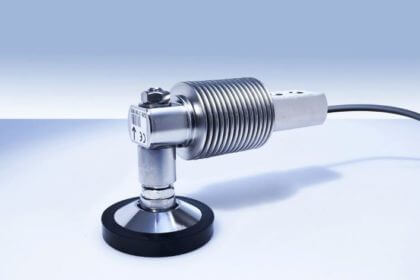
How can I do calibration of measurement of linearity of 150Kg weighing balance?