By using this site, you agree to the Privacy Policy and Terms of Use.
Accept
Inst ToolsInst ToolsInst Tools
  • Ask
  • Courses
  • Videos
  • Q & A
    • Interview
      • Instrumentation
      • Electronics
      • Electrical
      • Practical Questions
    • MCQ
      • Instrumentation MCQ
      • Electrical MCQ
      • Electronics MCQ
      • Control Systems MCQ
      • Analog Electronics MCQ
      • Digital Electronics MCQ
      • Power Electronics MCQ
      • Microprocessor MCQ
      • Multiple Choice Questions
  • EE
    • Electronics
      • Electronics Q & A
      • Electronic Basics
      • Electronic Devices & Circuits
      • Electronics Animation
      • Digital Electronics
    • Electrical
      • Electrical Basics
      • Electrical Q & A
      • Power Electronics
      • Electrical Machines
      • Electrical Animation
      • Power Systems
      • Switchgear & Protection
      • Transmission & Distribution
  • Measure
    • Control Valves
    • Calibration
    • Temperature
    • Pressure
    • Flow
    • Level
    • Analyzers
    • Switches
    • Vibration
    • Solenoid Valve
  • Control
    • PLC Tutorials
    • Control Systems
    • Safety Instrumented System (SIS)
    • Communication
    • Fire & Gas System
  • More
    • Design
    • Tools
    • Animation
    • Basics
    • Formulas
    • Standards
    • TextBooks
    • Common
    • Software
    • Excel Tools
    • Erection & Commissioning
    • Process Fundamentals
    • Videos
    • Books
Search
All rights reserved. Reproduction in whole or in part without written permission is prohibited.
Reading: Configure the Instruments in Flow Control Loop
Share
Notification Show More
Font ResizerAa
Inst ToolsInst Tools
Font ResizerAa
  • Ask
  • Courses
  • Videos
  • Q & A
  • EE
  • Measure
  • Control
  • More
Search
  • Ask
  • Courses
  • Videos
  • Q & A
    • Interview
    • MCQ
  • EE
    • Electronics
    • Electrical
  • Measure
    • Control Valves
    • Calibration
    • Temperature
    • Pressure
    • Flow
    • Level
    • Analyzers
    • Switches
    • Vibration
    • Solenoid Valve
  • Control
    • PLC Tutorials
    • Control Systems
    • Safety Instrumented System (SIS)
    • Communication
    • Fire & Gas System
  • More
    • Design
    • Tools
    • Animation
    • Basics
    • Formulas
    • Standards
    • TextBooks
    • Common
    • Software
    • Excel Tools
    • Erection & Commissioning
    • Process Fundamentals
    • Videos
    • Books
Follow US
All rights reserved. Reproduction in whole or in part without written permission is prohibited.
Inst Tools > Blog > Flow Measurement > Configure the Instruments in Flow Control Loop
Flow Measurement

Configure the Instruments in Flow Control Loop

Configure the instruments in flow control loop to sense and display process variable with the loop controller actuating two split-ranged control valves.

Last updated: November 2, 2023 1:11 pm
Editorial Staff
Share
3 Min Read
SHARE

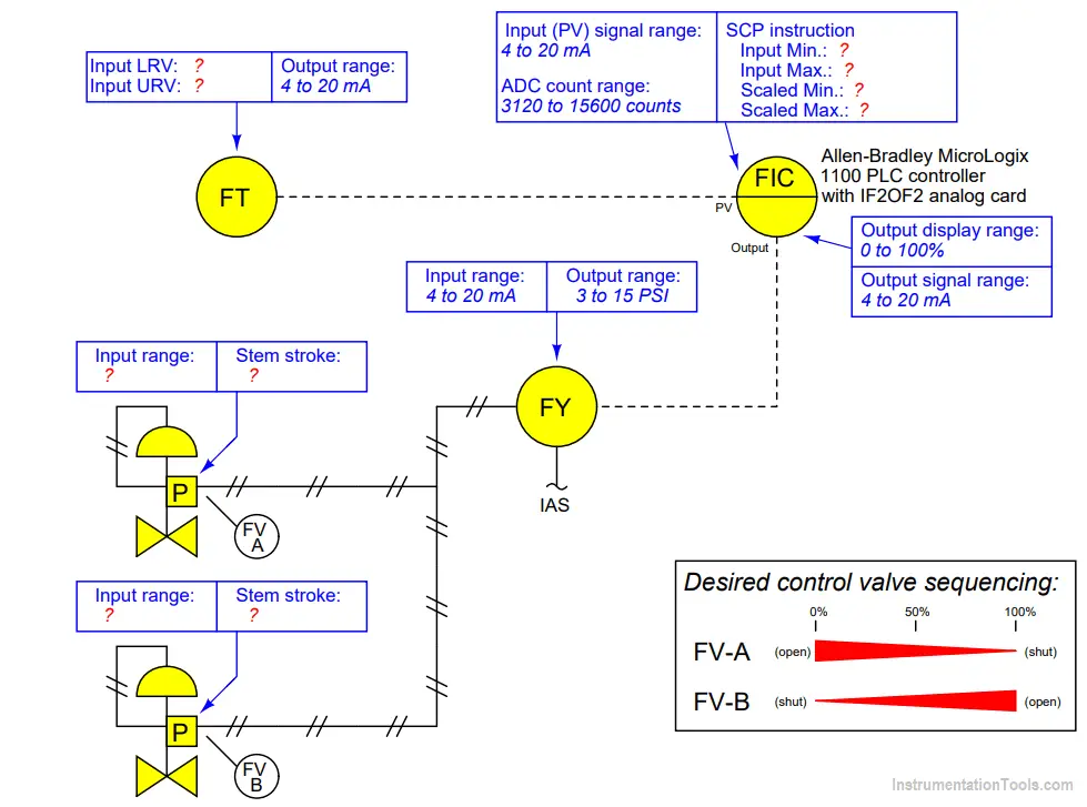
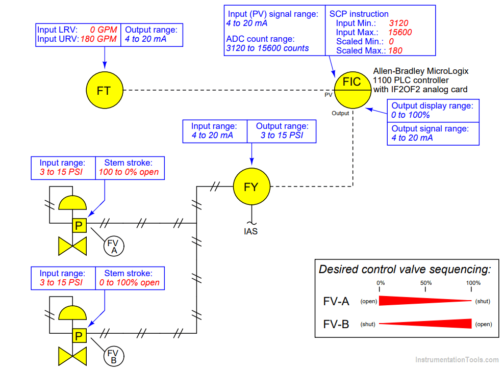
Suppose you are asked to configure the instruments in this flow control loop to sense and display process flow over a range of 0 to 180 gallons per minute (GPM), with the loop controller actuating two split-ranged control valves in a complementary sequence.

Contents
Configure the InstrumentsFlow Control Loop

A ā€œScale-with-Parametersā€ (SCP) instruction programmed into the Allen-Bradley controller is supposed to take the analog-to-digital converter’s raw count value as an input and scale it into units of GPM for the operator to read on a display:

Configure the InstrumentsConfigure the Instruments in Flow Control Loop

Write the proper range values inside the boxes near each instrument, showing the proper configuration for each instrument needed to achieve the desired result.

Suppose the controller displayed a flow of 129 GPM when the actual process flow was 135 GPM. First, identify two possible locations in this loop for a calibration error that would account for this discrepancy. Then, assuming only one fault, explain how you could positively determine the location of this calibration error with a single diagnostic test.

Suppose valve FV-A was 41% open and FV-B was 59% open when the controller output displayed 50%. First, identify two possible locations in this loop for a calibration error that would account for this discrepancy. Then, assuming only one fault, explain how you could positively determine the location of this calibration error with a single diagnostic test.

Flow Control Loop
Flow Loop

A PV measurement error could lie within the transmitter, or within the controller’s analog input. A single current measurement of the transmitter’s signal will tell you where the calibration error resides.

A valve positioning error affecting both control valves could lie within the I/P transducer or within the controller’s analog output. A single current measurement of the controller’s output signal will tell you where the calibration error resides.

If you liked this article, then please subscribe to our YouTube Channel for Instrumentation, Electrical, PLC, and SCADA video tutorials.

You can also follow us on Facebook and Twitter to receive daily updates.

Read Next:

  • Smart Transmitter Range
  • Field Instrument Errors
  • Process Control Loop
  • Failures in Control Valve
  • Split Range Control Loop
Don't Miss Our Updates
Be the first to get exclusive content straight to your email.
We promise not to spam you. You can unsubscribe at any time.
Invalid email address
You've successfully subscribed !
Oscillating Piston Flow Meters Working Principle
Heat Tracing Problems
Area Velocity Flow Meter Principle
Turbine Flow Meters Troubleshooting
All About Vortex Flow Meters
Share This Article
Facebook Whatsapp Whatsapp LinkedIn Copy Link
Share
Leave a Comment

Leave a Reply Cancel reply

Your email address will not be published. Required fields are marked *

Stay Connected

128.3kFollowersLike
69.1kFollowersFollow
206kSubscribersSubscribe
38kFollowersFollow

Latest

Top Non-PLC Certification Courses for Automation Professionals
Common
Things You Need to Know About DeviceNet
Communication
Why is IEC 60269 Important
Why is IEC 60269 Important? – Electrical Applications
Standards
NAMUR OPEN ARCHITECTURE
What is NAMUR OPEN ARCHITECTURE?
Control Systems

Related Articles

Water Cut Meter

What is Water Cut Meter?

Annubar flow principle

Different Types of Flow Elements

What is an Orifice Flange ?

What is an Orifice Flange? – Purpose and Applications

Hot wire Anemometer Principle

Hot Wire Anemometer Principle and Types

Flow Switch Working

Flow Switch : What is it? – Applications

Ultrasonic Flow meters Working Animation

Ultrasonic Flow Meters Animation

Reasons to Calibrate Flowmeters

Reasons to Calibrate Different Types of Flow Meters

Vortex flow meter Bluff Body

Types of Vortex Flow Meter Sensors

More Articles

LED Projects for Engineering Students

LED Projects for Engineering Students

GATE Instrumentation Questions and Answers

GATE Instrumentation Questions and Answers

pcb slip rings

Slip Rings in RoboticsĀ – Types, Applications, Advantages

different types of threads based on 4 standards

Different Types of Threads based on 4 Standards

PLC program for Sorting System by Size Example

PLC Based Product Sorting Machine System – Lift Control

Top Embedded Systems Projects for Engineers and Students

200 Top Embedded Systems Projects for Engineers and Students

Set the S5 timer value by a memory word

Set the S5 Timer Value by a Memory Word

Automatic Box Filling System using PLC Programming

Automatic Box Filling System using PLC Programming

//

Inst Tools

Sign Up for Our Newsletter

Subscribe to our newsletter to get our newest articles instantly!

[mc4wp_form id=”847″]

Follow US
All rights reserved. Reproduction in whole or in part without written permission is prohibited.
Welcome Back!

Sign in to your account

Username or Email Address
Password

Lost your password?