Inst ToolsInst ToolsInst Tools
  • Courses
  • Automation
    • PLC
    • Control System
    • Safety System
    • Communication
    • Fire & Gas System
  • Instrumentation
    • Design
    • Pressure
    • Temperature
    • Flow
    • Level
    • Vibration
    • Analyzer
    • Control Valve
    • Switch
    • Calibration
    • Erection & Commissioning
  • Interview
    • Instrumentation
    • Electrical
    • Electronics
    • Practical
  • Q&A
    • Instrumentation
    • Control System
    • Electrical
    • Electronics
    • Analog Electronics
    • Digital Electronics
    • Power Electronics
    • Microprocessor
Search
  • Books
  • Software
  • Projects
  • Process
  • Tools
  • Basics
  • Formula
  • Power Plant
  • Root Cause Analysis
  • Electrical Basics
  • Animation
  • Standards
  • 4-20 mA Course
  • Siemens PLC Course
Reading: What’s the problem with shock and vibration ?
Share
Notification Show More
Font ResizerAa
Inst ToolsInst Tools
Font ResizerAa
  • Courses
  • Design
  • PLC
  • Interview
  • Control System
Search
  • Courses
  • Automation
    • PLC
    • Control System
    • Safety System
    • Communication
    • Fire & Gas System
  • Instrumentation
    • Design
    • Pressure
    • Temperature
    • Flow
    • Level
    • Vibration
    • Analyzer
    • Control Valve
    • Switch
    • Calibration
    • Erection & Commissioning
  • Interview
    • Instrumentation
    • Electrical
    • Electronics
    • Practical
  • Q&A
    • Instrumentation
    • Control System
    • Electrical
    • Electronics
    • Analog Electronics
    • Digital Electronics
    • Power Electronics
    • Microprocessor
Follow US
All rights reserved. Reproduction in whole or in part without written permission is prohibited.
Inst Tools > Blog > Instrumentation Design > What’s the problem with shock and vibration ?

What’s the problem with shock and vibration ?

Last updated: December 22, 2018 1:22 am
Editorial Staff
Instrumentation Design
No Comments
Share
4 Min Read
SHARE

Shock and vibration are among the worst enemies of any pressure sensor. They are also the hardest to identify, and even then it can be very difficult to rectify the problem and avoid breakages. Remember: a pressure sensor is a highly sensitive and accurate measuring device, designed to measure pressure by the amount of deflection (stress, bending) of the diaphragm.

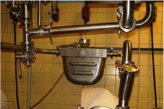
Consider a simple application: pumping liquid through a pipe with a pressure sensor installed via a T-junction to control the pump pressure. While this sounds simple enough, when everything is made from heavy-duty materials in order to be rugged, the only sensitive component is the sensor. And as always, the weakest link will fail, even when the failure is caused by another component.

Not only can the sensor be subject to shock and vibration from the liquid in the pipe, but also from the pipework itself. This vibration might be generated by the pump, valves opening and closing etc, but it can all be picked up by the sensor.

Seeking a cure

Identifying the shock and vibration frequencies is very complex and expensive, as we also have to look for harmonics that can be just as powerful. Even with these tests carried out it can be difficult to identify the source, relate it to the sensor and find a solution to cure the problem.

Even from a faulty sensor it is difficult to establish whether the failure has been caused by overpressure or vibration, as both errors will result in damage to the diaphragm or strain gauges.

Not only is it necessary to eliminate vibrations and shock, but also to look at the application outside its normal use. Shock and vibration can be caused in many ways. These include starting up of a pump, valve start/stopping, using a hammer on the pipe to loosen a seal (maintenance/service), pipe removal, dropping a pipe on a concrete floor etc.

The actual shock and vibration spectra will vary for each application, and is very much a “suck it and see” situation to find the right mounting. It is of course always best to avoid shock and vibration. This can be done by fitting rubber suspensions, using bellows, fitting the sensor further away from the source, checking the mass of material where the sensor is to be mounted, fixing all pipe work firmly, mounting the source on a rubber mount etc.

Sometimes the problem can be cured by changing the pressure sensor range as a thicker or thinner diaphragms will provide a different frequency response.

Reading the specs

Pressure sensor manufacturers will normally give two specifications:

Shock resistance, which is the ability of the sensor to withstand environmental shock, and is specified as g’s peak (milliseconds).

Vibration resistance is normally specified to a known standard in terms of overall g’s ms = minimum.

Don't Miss Our Updates
Be the first to get exclusive content straight to your email.
We promise not to spam you. You can unsubscribe at any time.
Invalid email address
You've successfully subscribed !

Continue Reading

Turbine-Compressor System Architecture
Instrument Panel Cooling Efficiency Enhancement
Design View of Supplying Process Control and Safety Systems
What are Impulse Lines? – Impulse Line Problems & Solutions
All About Vortex Flow Meters
What is Instrument DataSheet ?
Share This Article
Facebook Whatsapp Whatsapp LinkedIn Copy Link
Share
Leave a Comment

Leave a Reply Cancel reply

Your email address will not be published. Required fields are marked *

Stay Connected

128.3kFollowersLike
69.1kFollowersFollow
208kSubscribersSubscribe
38kFollowersFollow

Categories

Explore More

What to Choose RTD or Thermocouple ?
Top 10 Facts about HART Technology
Instrument Numbering Philosophy
Pull Up and Pull Down Switch Circuits
Process Variable Damping of Transmitter
How to Select a Rotameter? – Parameters and Applications
Heat Tracing Problems
Basics of Thermistors, Thermocouples and RTD’s

Keep Learning

Pressure Gauge Problems

Pressure Gauge Problems

Hammer Effect in Gauges

What is Hammer Effect in Gauges ?

Direct Acting Solenoid Valve

Top 5 Things for selecting a Solenoid Valve

Cable screen shall not be grounded

Cable Screen shall not be Grounded at Field Device ?

Control Room Design Guidelines

Control Room Design Guidelines

Air Cylinder Consumption Calculation for Control Valves

Air Cylinder Consumption Calculation for Control Valves

Orifice Beta

Why is Orifice Beta in between 0.3 to 0.7?

Instrument Air Calculations

Basic Calculations of Instrument Air

Learn More

Difference between Stepper Motor and Servo Motor

process gas chromatographs

Multi Column Gas Chromatograph

RFID Based Projects for Engineering Students

RFID Projects for Engineering Students

Voltage Regulator Circuit

Basics of Voltage Regulator

Fiber Optics Objective Questions and Answers

Fiber Optics Objective Questions and Answers

Instrumentation and Control General Specifications

Instrumentation and Control (I&C) General Specifications

Logic for Always ON and Always OFF bit

Always ON and OFF Bit using Ladder Logic and Statement List

Calibration of Temperature Sensor with Indicator

Calibration of Temperature Sensor with Indicator

Follow US
All rights reserved. Reproduction in whole or in part without written permission is prohibited.
Welcome Back!

Sign in to your account

Username or Email Address
Password

Lost your password?